
Image display apparatus, method, and program for automotive vehicle

a technology for automotive vehicles and display apparatuses, applied in the direction of instruments, television systems, static indicating devices, etc., can solve the problems of difficult grasping of stereoscopic distance, difficult to recognize the position of any obstacle from the top view image, and remarkable height-distortion

Inactive Publication Date: 2006-12-05
NISSAN MOTOR CO LTD
View PDF10 Cites 232 Cited by
  • Summary
  • Abstract
  • Description
  • Claims
  • Application Information

AI Technical Summary

Benefits of technology

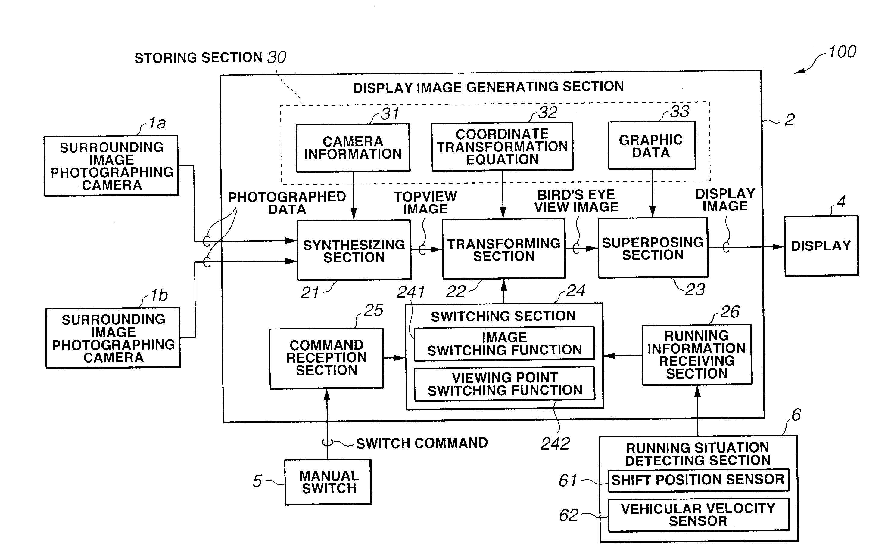
[0009]It is, therefore, an object of the present invention to provide image display apparatus, method, and program for an automotive vehicle in which the display of one of a plurality of display images, viz., a top view image and that of a bird's eye view image are switched therebetween to display the image suitable for the assistance of the driver's manipulation and which are, preferably, capable of displaying the image surrounding the vehicle viewed from the upper sky without image distortion.

Problems solved by technology

However, the top view image is an image whose viewing point of the camera equipped within the vehicle is moved to the upper sky over the vehicle, a distortion due to a deviation of the viewing point is included.
In addition, in a case where a three-dimensional vehicle with a height is projected onto a mounting plane (ground surface and soon) of the vehicle, a distortion in a height direction becomes remarkable and there is a disadvantage that a stereoscopic sense of distance is difficult to be grasped.
Especially, in a case where the driver drives the vehicle avoiding such obstacles as other vehicle, motor bicycle, or bicycle, there is an inconvenience that a position of any obstacle is not easily recognized from the top view image.
In this situation, the display of the top view image is inappropriate.
As described above, the display of only the top view image cannot sufficiently assist a driver's manipulation on the vehicle.

Method used


Image

  • Image display apparatus, method, and program for automotive vehicle
  • Image display apparatus, method, and program for automotive vehicle
  • Image display apparatus, method, and program for automotive vehicle

Examples


first embodiment

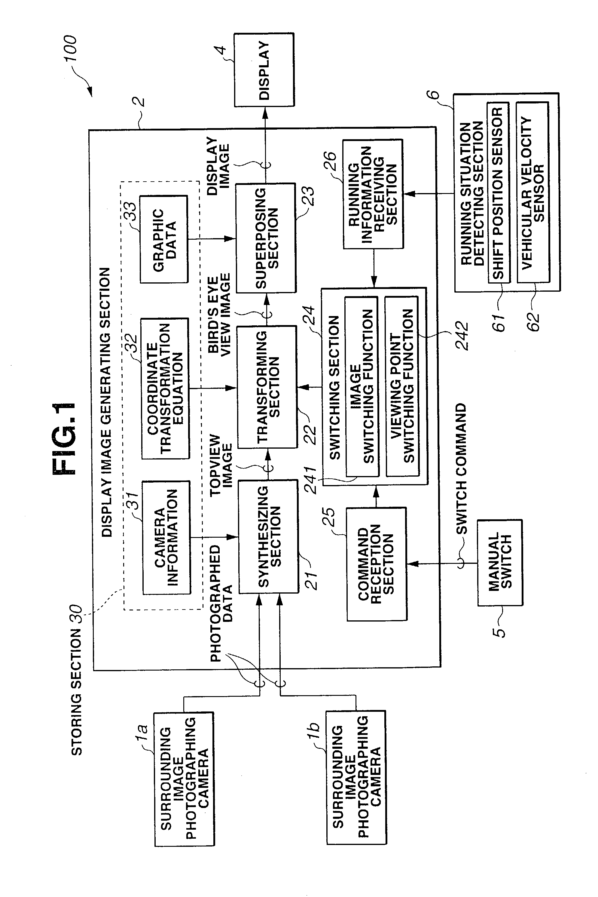
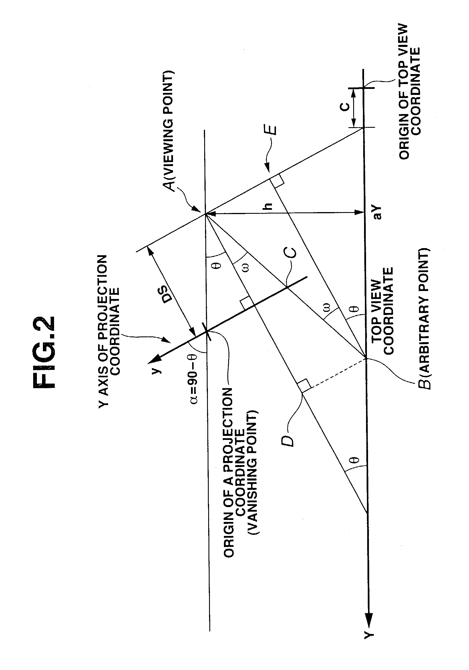
[0041]A vehicular image display apparatus 100 in a first preferred embodiment according to the present invention is an apparatus in which an image of an automotive vehicle and a surrounding of the vehicle looking down from a viewing point located at an upper sky above the vehicle is displayed on a display 4 installed within a vehicular passenger compartment. FIG. 1 shows a block diagram of the image display apparatus in the first preferred embodiment according to the present invention. FIGS. 2 and 3 show explanatory views for explaining a transform process from a top view image (a whole vehicular image, or plan view image) into a bird's eye view image (FIG. 2 corresponds to a Y-axis direction transformation process and FIG. 3 corresponds to an X-axis direction transformation process). As shown in FIG. 1, in the first preferred embodiment, image display apparatus 100 includes: a plurality of cameras (1a, 1b, - - - ) photographing the vehicle and the surrounding of the vehicle; a disp...

second embodiment

[0110]The image display apparatus in a second preferred embodiment according to the present invention will be described below. In the second embodiment, only a technique of switching the display image in switching section 24 is different from the first embodiment and the fundamental operation is generally the same as described in the first embodiment. Herein, a duplicate explanation from the first embodiment is avoided and only a difference point from the first embodiment will be described below.

[0111]When image switching function 241 of switching section 24 is activated in the first embodiment, image switching section 241 determines the form of the display image displayed in accordance with the running situation of the vehicle, the transforming process of transforming section 22 is controlled to switch the display image. On the other hand, in the second embodiment, viewing point switching function 242 of switching section 24 shown in FIG. 1 is activated. Viewing point switching fun...

third embodiment

[0116]FIG. 14 shows an arrangement of the image display apparatus in a third preferred embodiment according to the present invention. A plurality of cameras 1a, 1b, 1c, 1d, - - - are displayed on high positions of a vehicular body outer peripheral portion at appropriate spatial intervals to one another to photograph the vehicle surrounding. FIG. 15 shows an example of arrangement portions of cameras 1a through 1h. It is noted that although, in this embodiment, a photograph view angle of each camera 1a, 1b, - - - , 1h is mutually overlapped and eight cameras 1a through 1h are arranged on the vehicular (vehicle body) outer edge portion, the number of cameras and arrangement thereof to photograph the vehicular surrounding are not limited to this example of FIG. 15. In addition, the cameras 1a through 1h are arranged over the whole periphery of the vehicle to photograph the surrounding of the vehicle as shown in FIG. 15. However, the present invention is applicable to the vehicular imag...


PUM


Abstract

In image display apparatus, method, and program for an automotive vehicle, a surrounding of the vehicle is photographed, a plurality of display images are generated from a photographed data supplied from a photographing section, viewing points of the respective display images and looking down angles thereof being different from one another, one of the images generated is displayed through a display, and the display image generated and displayed through the display is switched to another one of the generated display images.

Description

BACKGROUND OF THE INVENTION[0001]1. Field of the Invention[0002]The present invention relates to image display apparatus, method, and program for an automotive vehicle which are capable of displaying the vehicle and a surrounding of the vehicle viewed from an upper sky through a looking down angle that the vehicle driver desires.[0003]2. Description of the Related Art[0004]A Japanese Patent Application First Publication No. Heisei 11-151975 published on Jun. 8, 1999 exemplifies a previously proposed image display apparatus for an automotive vehicle in which an image surrounding the vehicle is photographed by a camera equipped within the vehicle is displayed within a vehicular passenger compartment in order to assist an operation of the vehicle during an entrance of the vehicle in a parking lot or garage.[0005]It is possible to display directly the image photographed by the camera through a display in the previously proposed display apparatus. However, a viewing point of the camera i...

Claims


Application Information

Patent Timeline
IPC IPC(8): G09G5/00G08G1/16
CPCG08G1/16G08G1/168G06V20/56
Inventor TAKAHASHI, TOSHIAKIINOUE, HIROFUMIYAMAMOTO, YASUHIDE
Owner NISSAN MOTOR CO LTD
Learn More