Methods and apparatus for automatic magnetic compensation

a magnetic direction and automatic compensation technology, applied in the field of determination, can solve the problems of time-consuming and expensive processes of known compensation methods, requiring time-consuming manual compensation procedures, and limiting accuracy of known compensation methods

Inactive Publication Date: 2006-12-12
HONEYWELL INT INC
View PDF31 Cites 53 Cited by
  • Summary
  • Abstract
  • Description
  • Claims
  • Application Information

AI Technical Summary

Benefits of technology

[0006]In another aspect, a method of compensating a magnetometer affixed to a vehicle to obtain accurate magnetic heading information for a vehicle orientation is provided. The method comprises using the magnetometer to measure a distorted earth magnetic field relative to axes of the vehicle, determining a pitch and roll orientation of the vehicle axes with respect to the earth, and calculating the distortion of the earth's magnetic field for any relative angle between the vehicle axes and the earth's undistorted magnetic field. The method further comprises determining a magnetic heading based on the magnetometer measurement, adjusted by the pitch and roll orientation of the vehicle, and compensated for distortions of the earth's magnetic field.

Problems solved by technology

Known compensation methods are both time consuming and expensive processes.
These known compensation methods also provide a limited accuracy because the methods are typically optimized for only a single angle of magnetic inclination.
Some known modem electronic compasses utilize software or firmware algorithms for magnetic compensation, but even these devices generally require time-consuming manual compensation procedures to determine a set of optimum compensation coefficients for utilization when performing the algorithms.
Some low precision magnetometers are also known to exist, which provide quick automatic compensation techniques, but these techniques only provide a low accuracy compensation.
However, these compasses also incorporate initialization modes, which can be complex, and which must be repeated upon each usage of the compass.

Method used


Image

  • Methods and apparatus for automatic magnetic compensation
  • Methods and apparatus for automatic magnetic compensation
  • Methods and apparatus for automatic magnetic compensation

Examples


Embodiment Construction

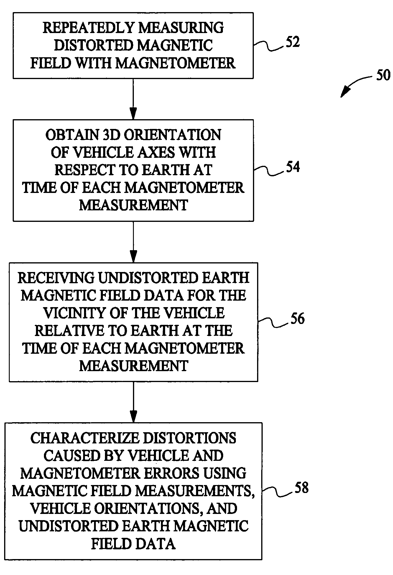
[0019]Methods and apparatus are herein described which automatically compensate a magnetic compass (e.g. a magnetometer) for local disturbances in the earth's magnetic field caused by a vehicle during normal vehicle operations. The methods and apparatus eliminate, or greatly reduce, time and expense associated with known methods for determination of magnetic compensation coefficients. Further, the methods and apparatus provide highly accurate, three dimensional compensation coefficients that are valid over all combinations of vehicle pitch, vehicle roll, vehicle heading, magnetic inclination, and magnetic declination.

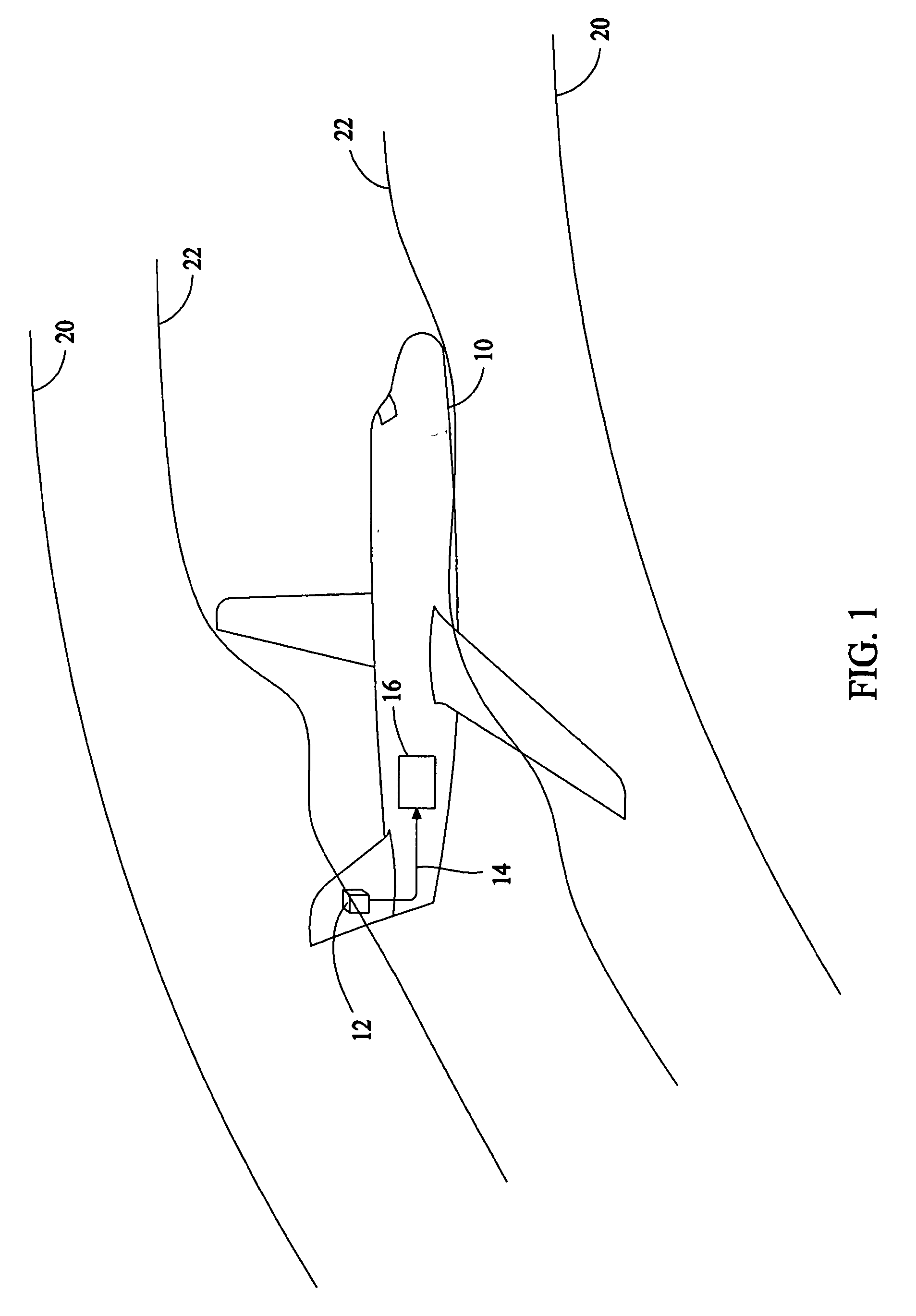
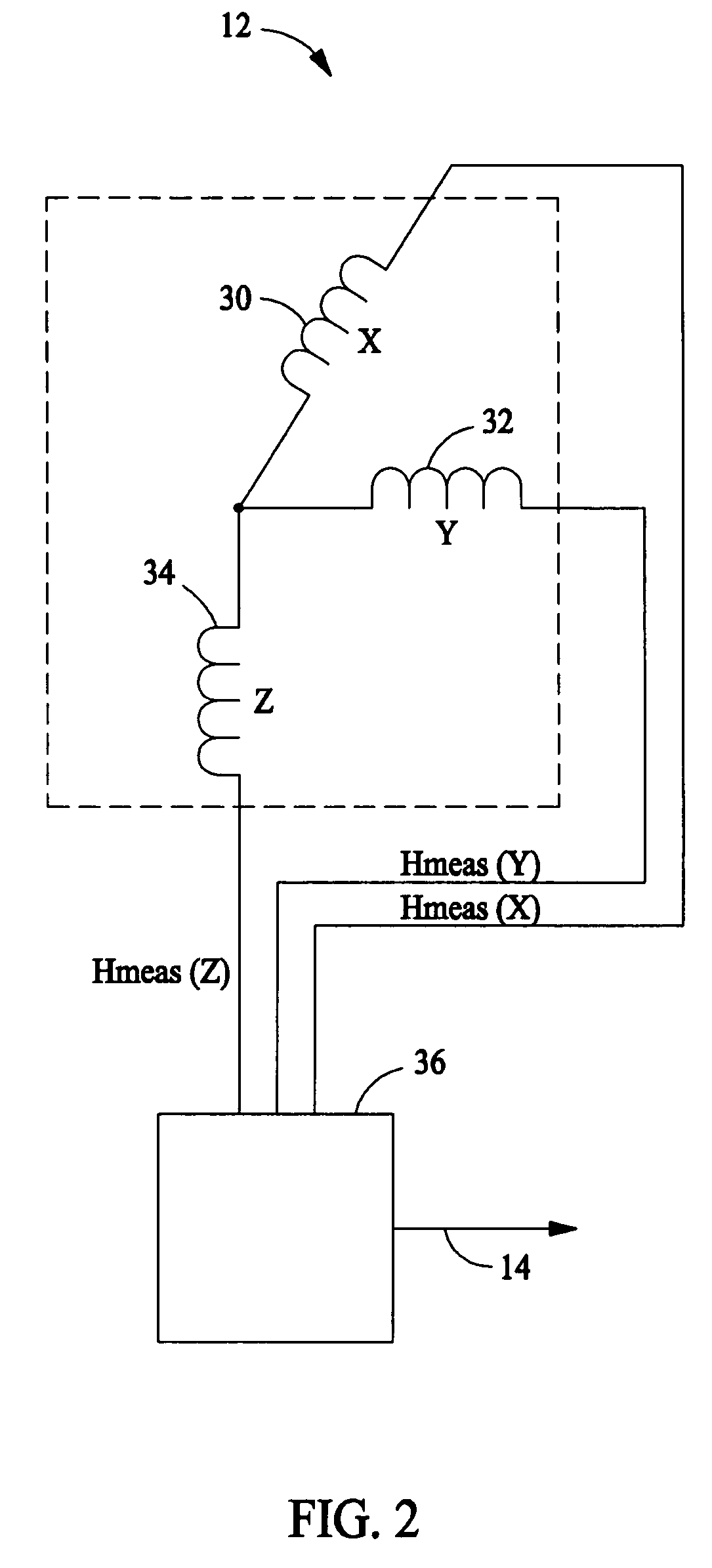
[0020]FIG. 1 illustrates an vehicle 10 equipped with a magnetometer 12 providing magnetic field strength signals 14. In one embodiment, magnetometer 12 provides magnetic field strength signals 14 representing a measurement of the earth's magnetic field to a magnetic compass compensation unit 16, which may be part of an aircraft navigation system, for example. Magnetomet...


PUM


Abstract

A method for characterizing distortions in the earth's magnetic field caused by a vehicle having a magnetometer affixed therein is described. The method includes repeatedly measuring the distorted magnetic field utilizing the magnetometer and obtaining a three-dimensional orientation of the vehicle axes with respect to the earth at a time of each magnetometer measurement. The method also includes receiving undistorted earth magnetic field data for the vicinity of the vehicle relative to the earth at the time of each magnetometer measurement and characterizing distortions caused by one or more of the vehicle and magnetometer errors utilizing the magnetic field measurements, the orientations of the vehicle, and the undistorted earth magnetic field data.

Description

CROSS REFERENCE TO RELATED APPLICATIONS[0001]This application is a Continuation-in-Part Application of U.S. patent application Ser. No. 10 / 724,974, filed Dec. 1, 2003 now U.S. Pat. No. 6,860,023, which claims priority of Provisional Application Ser. No. 60 / 436,980 filed Dec. 30, 2002, both of which are hereby incorporated by reference.BACKGROUND OF THE INVENTION[0002]This invention relates generally to determination of direction through magnetic direction indication, and more specifically to methods and apparatus for compensation of magnetic direction indications to account for local magnetic disturbances.[0003]Magnetic direction indicators (e.g., magnetic compasses, magnetometers) are typically compensated to account for local disturbances in an ambient magnetic field caused by nearby magnetic objects, for example, ferrous materials, and magnetic fields generated by electrical currents. Known compensation methods are both time consuming and expensive processes. These known compensa...

Claims


Application Information

Patent Timeline
Patent Type & Authority Patents(United States)
IPC IPC(8): G01C17/38
CPCG01C17/38
Inventor MANFRED, MARK T.
Owner HONEYWELL INT INC
Why Eureka
Try Eureka