Sliding blade microtome

a sliding blade and microtome technology, applied in the field of microtomes, can solve the problems of lack of specimen support, slow cutting speed, and inability to fully utilize vibratome, and achieve the effect of preventing the leakage of buffer medium

Active Publication Date: 2006-12-12
KONG GEORGE Y +1
View PDF19 Cites 26 Cited by
  • Summary
  • Abstract
  • Description
  • Claims
  • Application Information

AI Technical Summary

Benefits of technology

[0009]Ideally the first end and a portion of the syringe shaft are disposed in a bath through a syringe aperture. The syringe aperture is completely submerged under a buffer medium, which is held in the bath. A sealant ring seals the gap between the specimen syringe and the syringe aperture of the bath, thereby preventing the buffer medium from leaking.

Problems solved by technology

Though vibratomes have advanced the study of live and fresh tissues, there are disadvantages, such as slow cutting speeds, inconsistent slice thickness, lack of a support for the specimen and the presence of chatter marks on the sliced specimen, that leave the vibratome lacking as a fully efficient microtome.

Method used


Image

  • Sliding blade microtome
  • Sliding blade microtome
  • Sliding blade microtome

Examples


first embodiment

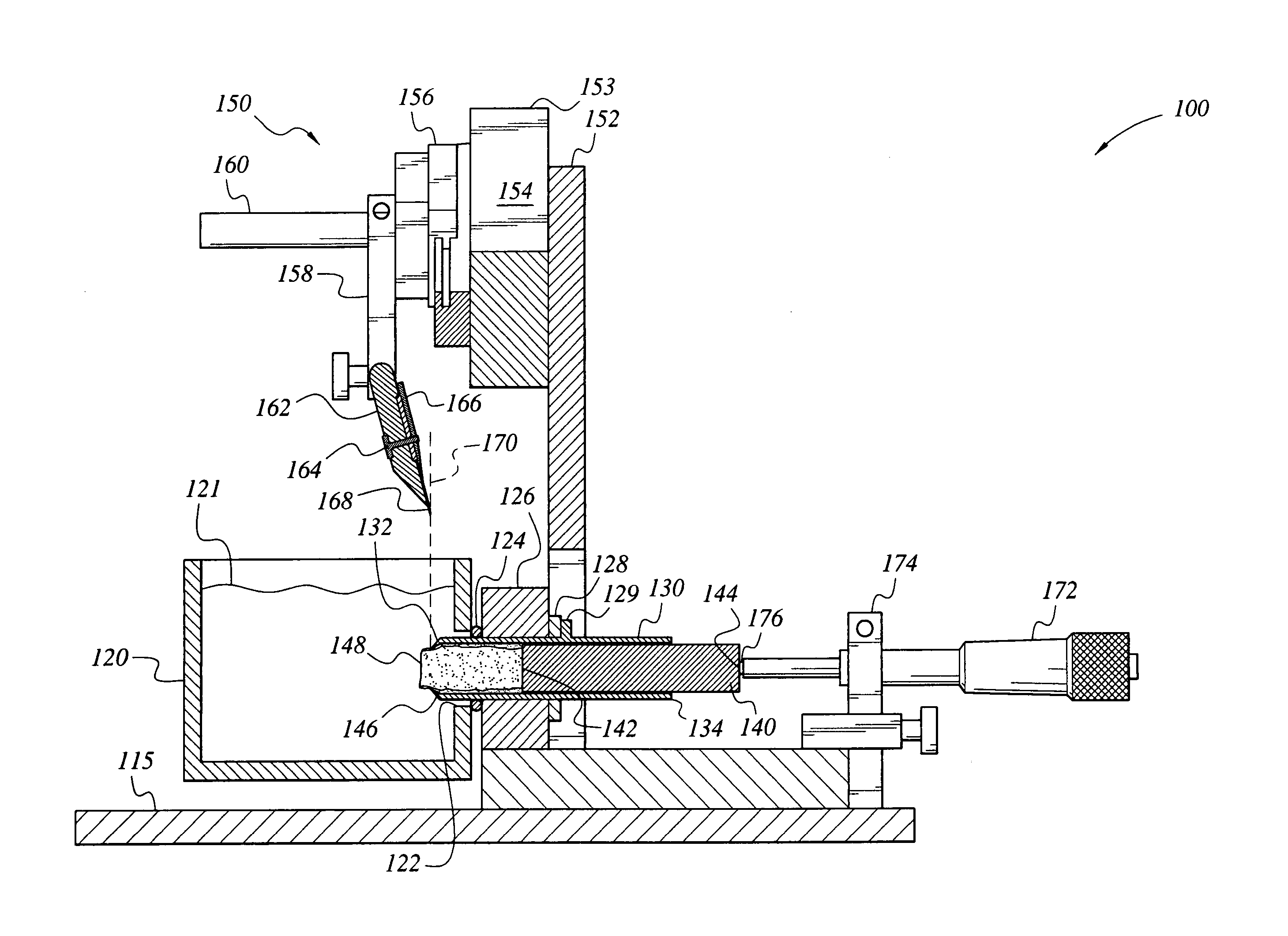
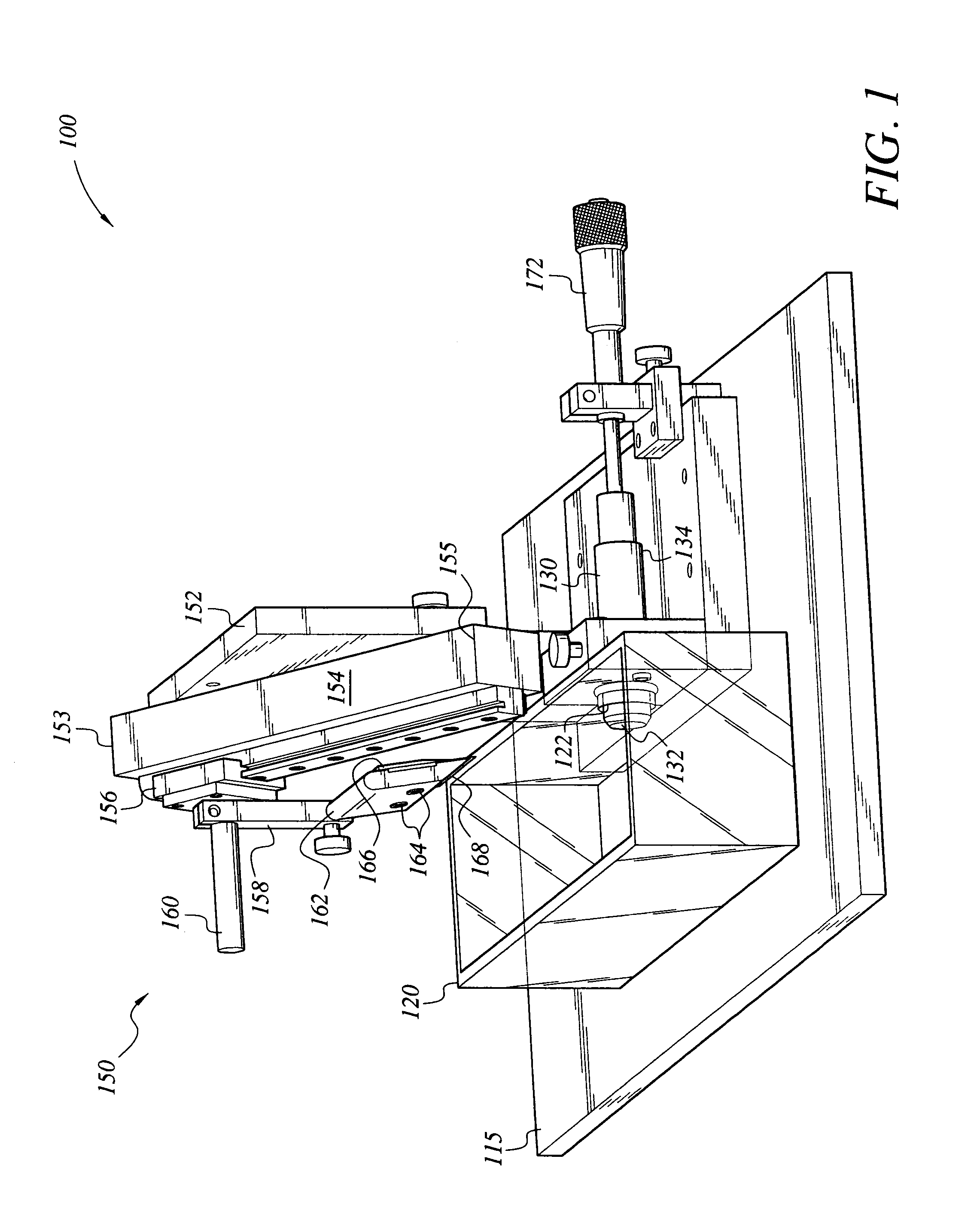
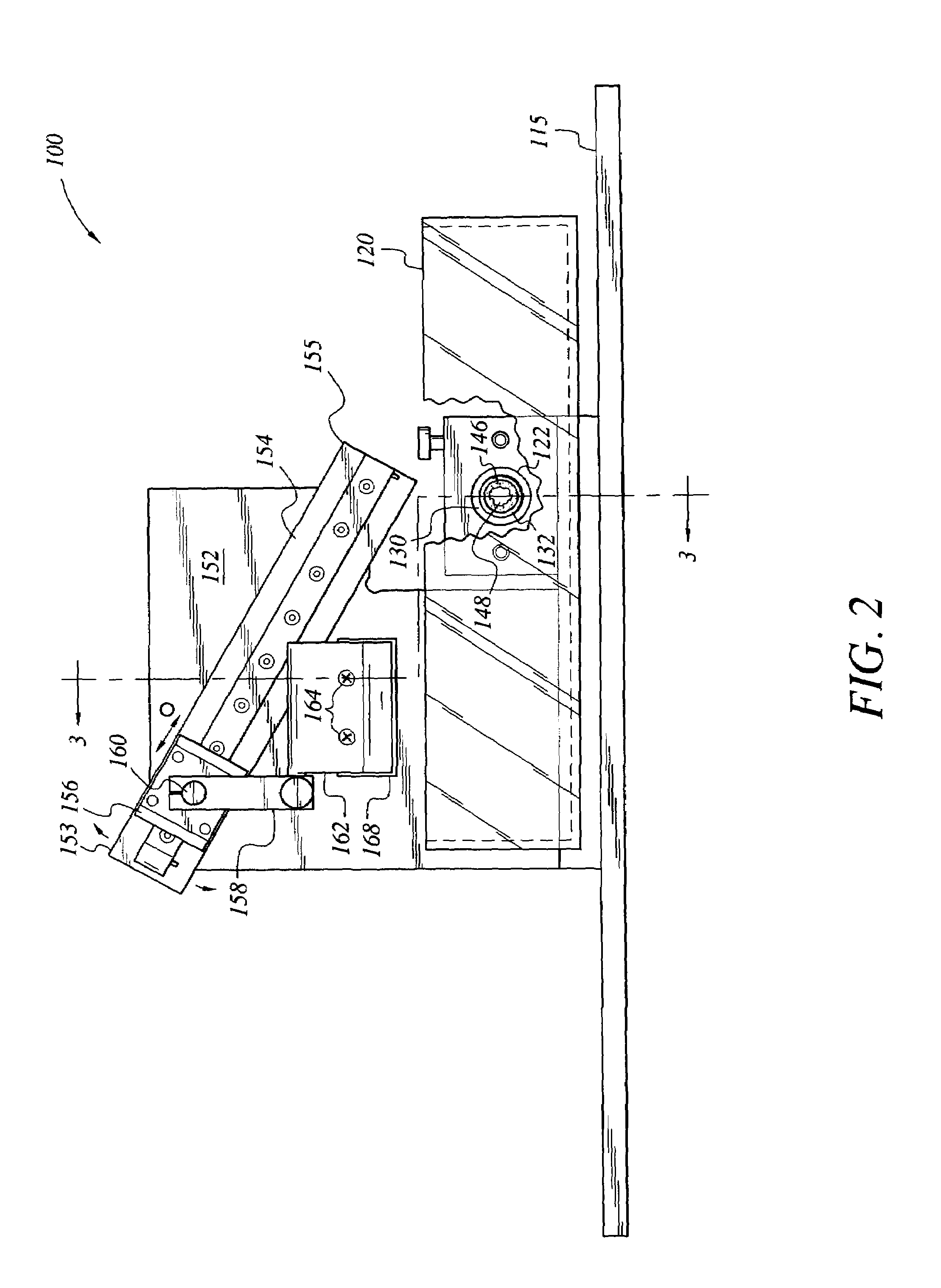
[0017]The present invention is a sliding blade microtome, which is designated as 100 in the figures. The sliding blade microtome 100 is a tissue specimen-cutting device for slicing live and pre-fixed tissue. The microtome 100 has a base 115 for supporting a specimen syringe 130 having a first end 132 and a second end 134, a bath 120 having a syringe aperture 122, an adjustable cutting mechanism 150 and a micrometer drive 172. The first end 132 of the specimen syringe 130 is ideally disposed through the syringe aperture 122 of the bath 120. The second end 134 of the syringe 130 is disposed adjacent the micrometer drive 172.

[0018]Referring to FIGS. 1–3, the cutting mechanism 150 is shown comprising a mounting accessory 156 having an axis rod 160, a cross clamp 158, a blade holder 162 and a blade 168. The cross clamp 158 is disposed on the axis rod 160 of the mounting accessory 156. The cross clamp 158 serves as a support to which the blade holder 162 is pivotally attached. The blade 1...

second embodiment

[0028]FIG. 4 shows the microtome, which is an automated microtome 200 that drives the plunger 236 through the syringe 130 via a control unit 220, sensors 240, 250, motors 242, 252, lead screw blocks 244, 254 and lead screw 246, 256. The motor 242 drives cutting mechanism 232 through lead screw 246 and lead screw block 244. The motor 252 operates the plunger 236, moving it forward using lead screw 256 and lead screw block 254. The control unit 220 monitors the positions of the lead screw blocks 244, 254 through sensors 240, 250, respectively, and sends commands to control the motors 242, 252, respectively.

[0029]The microtomes 100, 200 differ in how the plungers 140 and 236, respectively, are pushed out of the syringe 130. However, both microtomes 100, 200 hold and support the specimen 148 using the specimen syringe 130. Also, both have the compressed lip at the first end 132 to compress the specimen 148 prior to being sliced by the blade 168. Furthermore, the cutting mechanism 150, 2...


PUM

PropertyMeasurementUnit
diameteraaaaaaaaaa
acute angleaaaaaaaaaa
light microscopyaaaaaaaaaa

Abstract

The sliding blade microtome is a tissue specimen cutting device including a specimen syringe and an adjustable cutting mechanism for diagonally slicing the specimen. The specimen syringe is a cylindrical shaft having a first end and a second end for holding and supporting a specimen. The first end has a diameter that is smaller than the diameter of the shaft, forming a compressed lip for applying pressure on the specimen prior to slicing by the blade. The pressure used to compress the gelatin and the specimen holds the gelatin and the specimen in a sturdy position to slice the specimen to precision without chatter marks. The specimen is pushed out of the first end of the specimen syringe by a motor mechanism or a manually adjustable micrometer drive.

Description

BACKGROUND OF THE INVENTION[0001]1. Field of the Invention[0002]The present invention relates to microtomes, more specifically to a sliding blade microtome.[0003]2. Description of the Related Art[0004]Much modern scientific research involves microscopic analysis. Much of today's microscopic analysis requires tissues to be prepared by devices that provide thin specimens, such as microtomes. Many microtomes are specifically designed for preparing specimen for certain types of microscopes. For instance, rotary microtomes cut thin sections of specimen for light microscopy and ultramicrotomes are used to prepare ultrathin sections for light and electron microscopy. Live tissues, such as brain or liver tissues, are prepared by oscillating or vibrating blade microtomes called vibratomes. Vibratomes are currently employed in biomedical studies such as electrophysiology recording, organotypic tissue culture and immunohistochemistry experiments. Though vibratomes have advanced the study of li...

Claims


Application Information

Patent Timeline
Patent Type & Authority Patents(United States)
IPC IPC(8): B26D1/10
CPCG01N1/06Y10T83/647Y10T83/6492Y10T83/6496Y10T83/6544
Inventor KONG, GEORGE Y.KONG, JIAN-QIANG
Owner KONG GEORGE Y
Why Eureka
Try Eureka