Bullet-resistant hand-held defensive object

a technology for hand-held defensive objects and bullet-resistant objects, which is applied in the direction of shields, protective equipment, transportation and packaging, etc., can solve the problems of officer being caught totally by surprise, her safety in any way in danger, and unaware of such an even

Inactive Publication Date: 2006-12-12
MAGSHIELD TECH
View PDF19 Cites 31 Cited by
  • Summary
  • Abstract
  • Description
  • Claims
  • Application Information

AI Technical Summary

Benefits of technology

[0010]One such function is completely oriented to the conventional needs of the police officer, namely having a convenient writing surface and storage container that is sufficiently lightweight to be used on a portable basis, adjacent the vehicle that he or she has stopped. Another such function is to provide a bullet-resistant device which is readily placed between the officer's vulnerable body parts, such as his head, race, neck and hands, and the driver or other occupant of the vehicle who may point a weapon at the officer in a threatening manner.
[0022]Another object of the present invention is to provide capability for countering violent actions of a suspect and / or provide for subsequent identification of the suspect with devices protected internally within the bullet resistant box.

Problems solved by technology

Unfortunately, under the law in many states, the police officer approaching an occupied vehicle during a traffic investigator is not permitted to approach the vehicle with his handgun drawn unless he or she has probable cause to believe that he or she is in danger of being attacked.
Most often, it is not immediately apparent to the officer approaching such a vehicle that his or her safety is in any way in danger.
Consequently, in many cases where the driver or other occupant or a vehicle pulls a gun and fires at the approaching officer or officer positioned adjacent the drivers open window, the officer is caught totally by surprise and unaware that such an event will occur.
Otherwise they will not be used and thus irrespective of their effectiveness, will not serve to reduce this problem because officers will simply refuse to use them.

Method used


Image

  • Bullet-resistant hand-held defensive object
  • Bullet-resistant hand-held defensive object
  • Bullet-resistant hand-held defensive object

Examples


Embodiment Construction

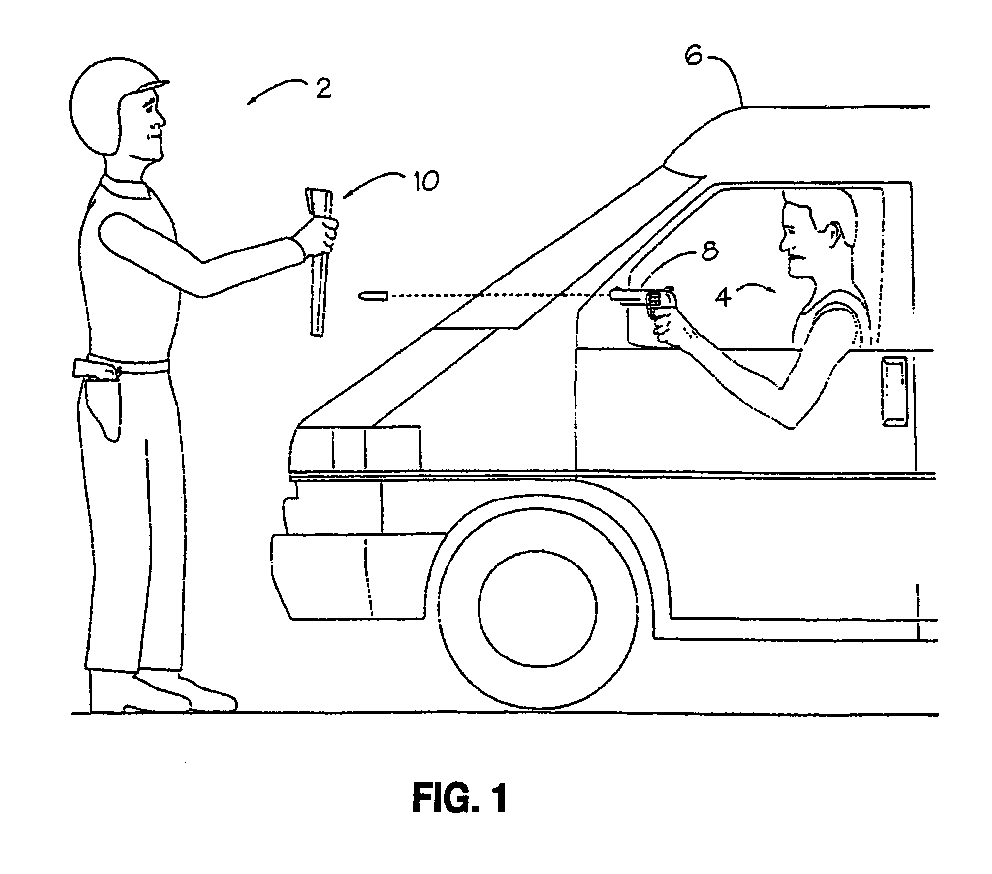
[0052]Referring now to the accompanying figures, it will be seen that a typical scenario where the present invention may be advantageously employed is illustrated in FIG. 1. As shown therein, a law enforcement officer 2 has approached the driver (or other occupant) 4 of a stopped vehicle 6, such as for the purpose of issuing a summons to appear before a magistrate or other judicial officer, due to an alleged traffic violation. Officer 2 may be wearing a bulletproof vest, although the present invention may be utilized even if no such vest is being worn. Unexpectedly, the driver 4 deploys a firearm 8 (for example, a handgun) pointed in the direction of the officer and specifically at the officer's upper body region and especially his neck or head.

[0053]At this point, officer 2, who is carrying a head and neck shield in the form of a protective shield 10, configured in accordance with the present invention, places that shield in front of his face so that it is interposed between the li...


PUM


Abstract

A bullet-resistant defensive device is disclosed made up of layers of bullet resistant material layered together and connected along their peripheral edge on a frame to form a planar shield. The shield so formed works such that a bullet striking the shield causes the layered bullet resistant material to flex thereby dissipating the force of the bullet, the material when it stretches transfers the force of the bullet from a shear mode to a tensile mode. One preferred embodiment incorporates the invention into a clipboard box for use by police officers for protecting against head, neck and hand wounds from handguns fired at close range from vehicles. The hand-held, bullet resistant clipboard box holds documents and writing implements, and the bullet-resistant material is located within the clipboard box interior cavity and configured for catching a fired bullet before it can pass through the entire clipboard.

Description

[0001]This Application claims the benefit of U.S. Provisioned Application Ser. No. 60 / 482,434; filed on Jun. 4, 2003 and having the same title as this Application.BACKGROUND OF THE INVENTION[0002]1. Field of the Invention[0003]The present invention relates to a bullet-resistant hand-held defensive object, such as a head and neck shield, that may be used by law enforcement personnel to protect portions of the body, such as the head and neck, against injury from being shot at close range, as may occur when a police officer approaches a stopped vehicle.[0004]The present invention pertains more specifically to a bullet resistant clipboard box or some similar portable shield like object containing a bullet-resistant material, for example, a plurality of layers of KEVLAR, to protect against injury to parts of the body not otherwise normally protected by other defensive devices, such as bullet-proof vests and the like.[0005]2. Background Description[0006]It is well known that the use of ha...

Claims


Application Information

Patent Timeline
Patent Type & Authority Patents(United States)
IPC IPC(8): F41H5/00F41H5/08F41H13/00
CPCF41H5/08F41H13/0087F41H13/0025Y10T428/24595
Inventor IMBLUM, RAYSODARO, DAVID
Owner MAGSHIELD TECH
Why Eureka
Try Eureka