Engine control system

a control system and engine technology, applied in the direction of electric control, machines/engines, liquid fuel feeders, etc., can solve the problems of large small detection error of ignition timing, and inability to accurately detect ignition timing

Active Publication Date: 2006-12-12
DENSO CORP
View PDF7 Cites 25 Cited by
  • Summary
  • Abstract
  • Description
  • Claims
  • Application Information

AI Technical Summary

Problems solved by technology

Thus, detecting error of the ignition timing is small to accurately detect the ignition timing.
When the method for detecting the ignition timing is applied to the premix combustion, the following problem will arise.
Thus, the detecting error of the ignition timing becomes large.

Method used


Image

  • Engine control system
  • Engine control system
  • Engine control system

Examples


first embodiment

[First Embodiment]

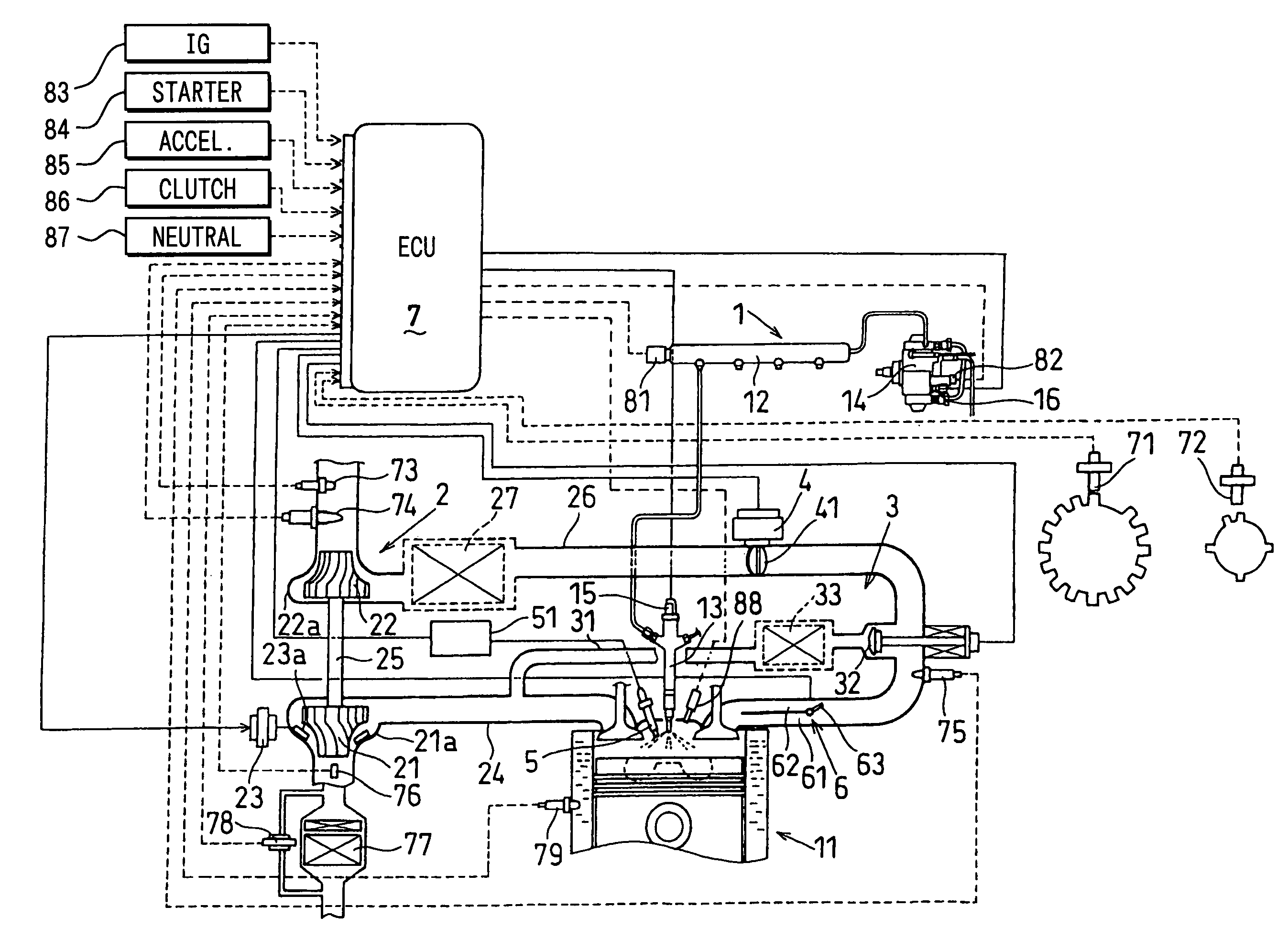
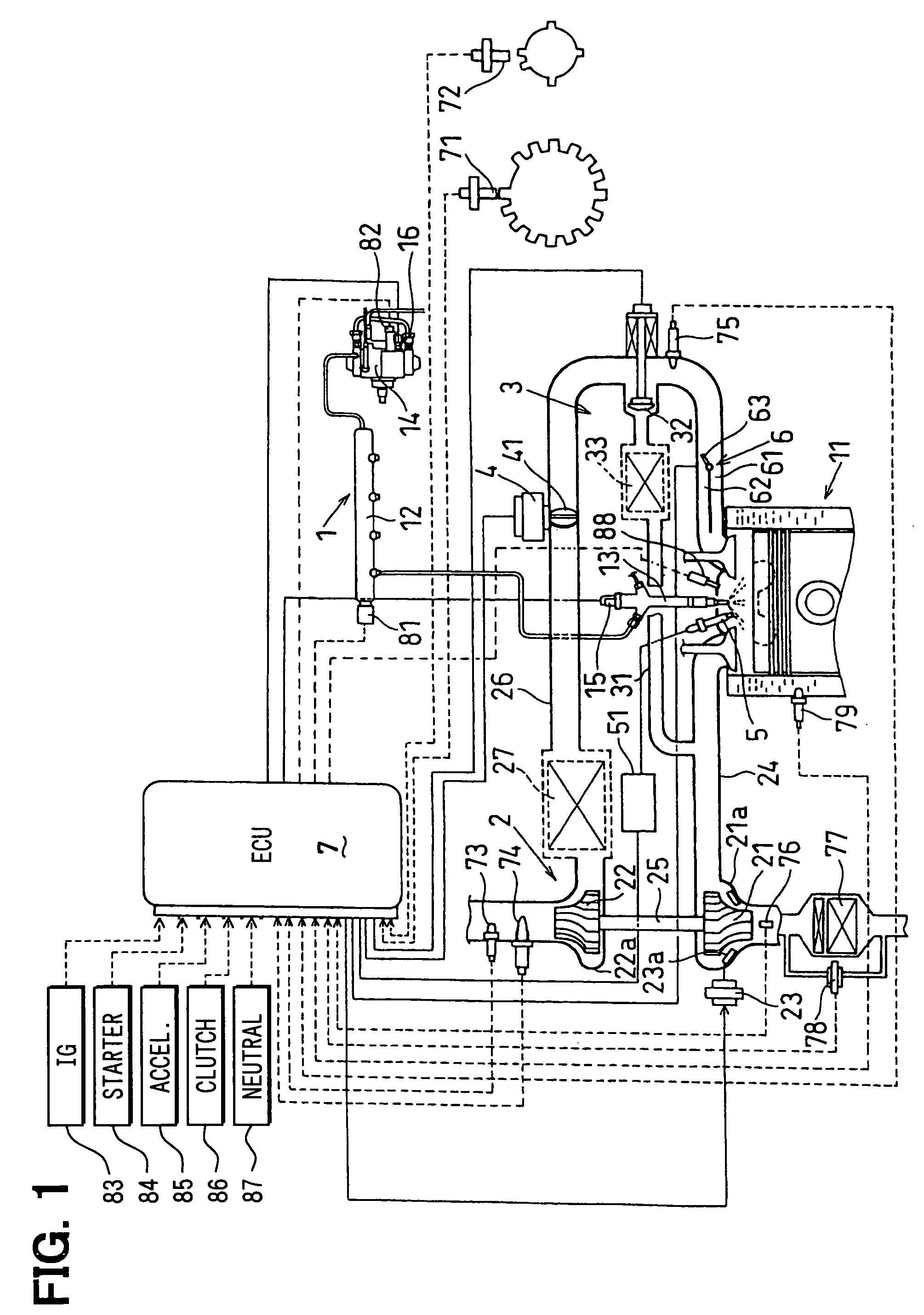
[0029]FIG. 1 is a schematic view of an engine control system. The engine control system includes a plurality of control subjects and an electric control unit (ECU) 7 which controls the control subjects. The control subjects comprises a common-rail fuel injection apparatus 1, a super charger 2, an EGR (Exhaust Gas Recirculation) apparatus 3, an intake throttle, a glow plug 5, and a swirl control apparatus 6. In this first embodiment, the ECU 7 controls the common-rail fuel injection apparatus 1.

[0030]The common-rail apparatus 1 supplies fuel to a diesel engine, which is referred to as an engine, and comprises a common-rail 12, an injector 13, a supply pump 14, and the like.

[0031]An outlet of the supply pump 14 is connected to the common-rail 12 which accumulates the fuel in a high pressure. Each of the injector 13 is fluidly connected to the common-rail 12 through a supply pipe.

[0032]Each of the injector 13 is respectively mounted to each cylinder of the engine 11. ...

second embodiment

[Second Embodiment]

[0092]Referring to FIG. 7, a second embodiment is described hereinafter.

[0093]The combustion mode determining means in the first embodiment determines whether the combustion mode is the diffuse combustion or the premix combustion based on the engine speed and the engine load. Even in the same engine driving condition (such as the engine speed or the engine load), the combustion mode may be changed to change the heat-release-rate due to a delay of air during transitional period.

[0094]According to the second embodiment, a graphic calculation means is provided. The graphic calculation means computes a graphic form or a graphic area of the heat-release-rate, on which it is determined whether the combustion mode of the engine 11 is the diffuse combustion mode or the premix combustion mode.

[0095]Specifically, the whole of the graphic form may be identified by the well-known pattern recognition technique, or a part of the graphic form in which the heat-release-rate is hi...

third embodiment

[Third Embodiment]

[0098]Referring to FIG. 8, a third embodiment is described hereinafter.

[0099]The combustion mode determining means in the third embodiment determines whether the combustion mode of the engine 11 is the diffuse combustion mode or the premix combustion mode based on a predetermined period β2 in which the heat-release-rate exceeds a predetermined threshold β1. The threshold β1 may be the same value as the ignition determining value α.

[0100]Specifically, as shown in FIG. 8, when the predetermined period β2 is longer than a determining period β3 (β2>β3), it is determined that the combustion mode is the diffuse combustion mode. When the predetermined period β2 is less than or equal to the determining period β3 ((β2≦β3), it is determined that the combustion mode is the premix combustion mode.

[0101]In FIG. 8, a heavy line A represents the heat-release-ratio in the diffuse combustion mode, and a thin line B represents the heat-release-rate in the premix combustion mode.


PUM


Abstract

When a combustion mode of an engine is a diffuse combustion mode in which an initial rising inclination of a heat-release-rate is steep, an electronic control unit (ECU) calculates an ignition timing in which the heat-release-rate exceeds an ignition determining value. Thus, even if a cylinder pressure sensor has a gain deviation or an offset deviation, the ignition timing is accurately detected to control the injection start timing. When the combustion mode is a premix combustion mode in which the initial rising inclination of the heat-release-rate is moderate, a peak arising timing of the heat-release-rate is calculated. Thus, the peak arising timing is accurately detected to control the injection start timing.

Description

CROSS REFERENCE TO RELATED APPLICATIONS[0001]This application is based on Japanese Patent Application No. 2004-334811 filed on Nov. 18, 2004, the disclosure of which is incorporated herein by reference.FIELD OF THE INVENTION[0002]The present invention relates to an engine control system which performs a feedback control on a control subject relating to an engine control based on a pressure in a combustion chamber of the engine. The pressure in the combustion chamber is detected by a cylinder pressure sensor. The control subject is such as a fuel injection timing, a fuel injection amount, a valve opening of an EGR apparatus, and a turbo opening of a turbocharger. Especially, the present invention relates to the engine control system which is able to change combustion mode which varies in an initial rising inclination character of a heat-release-rate.BACKGROUND OF THE INVENTION[0003]JP-2004-100567A (EP-1538325A1) shows that the ignition timing is detected by a cylinder pressure sensor...

Claims


Application Information

Patent Timeline
Patent Type & Authority Patents(United States)
IPC IPC(8): F02D41/40
CPCF02D35/023F02D35/028F02D41/3035F02D41/401F02B1/12F02B23/101F02B29/0406F02B31/06F02B2075/125F02D23/02F02D41/0052F02D41/3836F02D41/40F02M25/0707F02M25/0727F02P5/153F02P19/02Y02T10/44Y02T10/123F02M26/05F02M26/23Y02T10/12Y02T10/40
Inventor NORIMOTO, SUMIKOHARAGUCHI, HIROSHIUMEHARA, AKIRATAKEMOTO, EIJI
Owner DENSO CORP
Why Eureka
Try Eureka