

Bendable/twistable rolling conveyor guide
a conveyor guide and twisting technology, applied in the direction of conveyor parts, rollers, roller-ways, etc., can solve problems such as product spillage or skewed orientation, package jamming and possible damage, line stoppage,
- Summary
- Abstract
- Description
- Claims
- Application Information
AI Technical Summary
Benefits of technology
Problems solved by technology
Method used
Image

Examples
Embodiment Construction
,” one will understand how the features of this conveyor guide provide advantages, which include ease of assembly and ability to be bent and twisted by the purchaser.
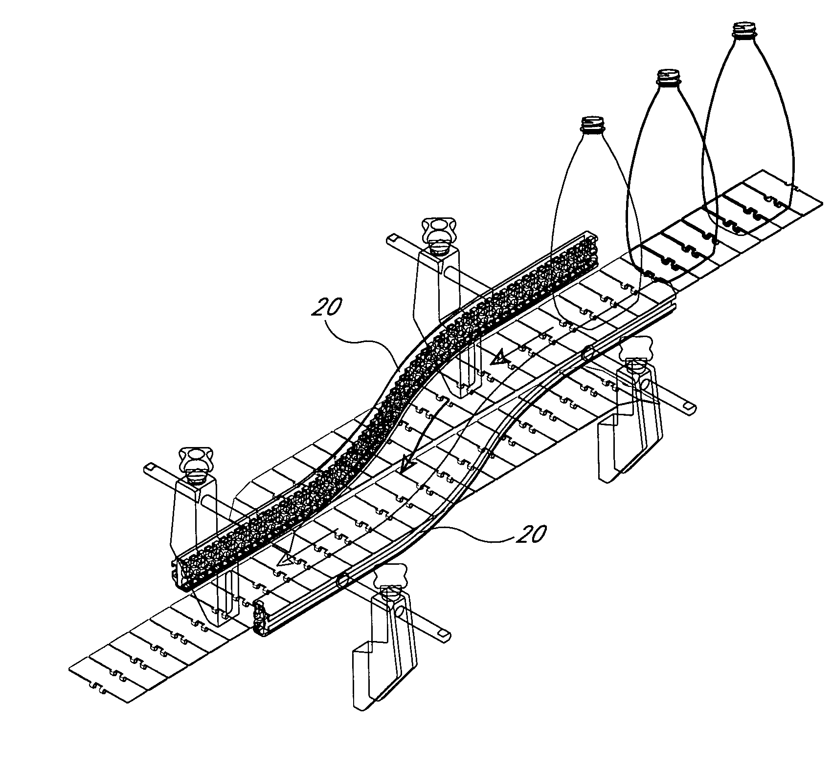
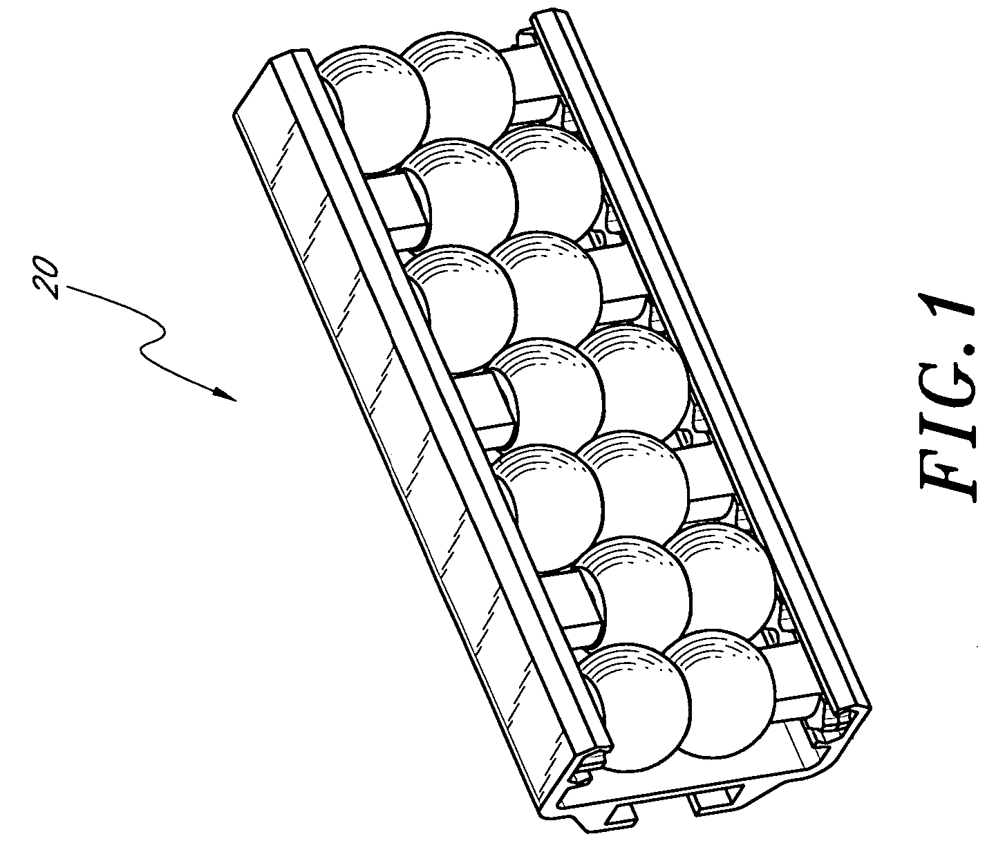
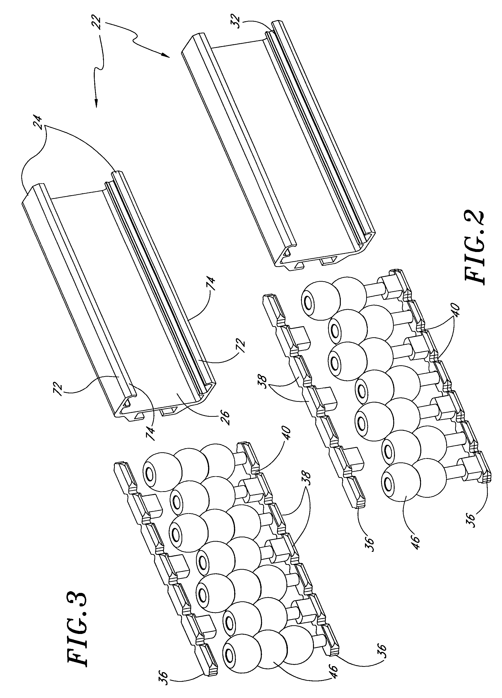
[0016]The present bendable / twistable rolling conveyor guide is easy to bend and twist, and is thus readily adaptable for use in any conveyor layout. In one embodiment, the bendable / twistable rolling conveyor guide includes any number of axles disposed between a pair of chain-like axle-positioning members. The axles serve as mounting points for rotatable elements such as rollers or beads. The axles and / or spacers may be molded integrally with the axle-positioning members. The axle-positioning members slidably engage two channels in a structural support member. The axle-positioning members are rigid but readily bendable and twistable. Evenly spaced notches cut in the edges of the axle-positioning member contribute to the ready bendability and twistability of the axle-positioning members. The shape of the notches ensures t...
PUM
 Abstract
Description
Claims
Application Information