Coupling apparatus

a technology of coupling apparatus and bottom end cap, which is applied in the direction of couplings, sealing/packing, and wellbore/well accessories, etc., can solve the problems of reducing affecting the service life of the apparatus, so as to reduce the chance of breakage and reduce the chance of leakage

Inactive Publication Date: 2006-12-12
WEATHERFORD TECH HLDG LLC
View PDF20 Cites 42 Cited by
  • Summary
  • Abstract
  • Description
  • Claims
  • Application Information

AI Technical Summary

Benefits of technology

[0051]The eighth aspect of the invention provides a flexible joint between a downhole tubular, and a pump tubular. When in use, the pump tubular directs fluid from a pump into the downhole tubular. By allowing relative axial movement between these two parts, we reduce the chance of breakage in the event that the downhole tubular sticks when it is being lowered into a borehole.
[0052]The pump tubular is preferable received in the downhole tubular. This reduces the chance of leakage.

Problems solved by technology

This arrangement suffers from a number of problems.
Firstly the apparatus has a large number of working parts.
Secondly it can be difficult and time consuming to rotate the bottom end cap.

Method used


Image

  • Coupling apparatus
  • Coupling apparatus
  • Coupling apparatus

Examples


Embodiment Construction

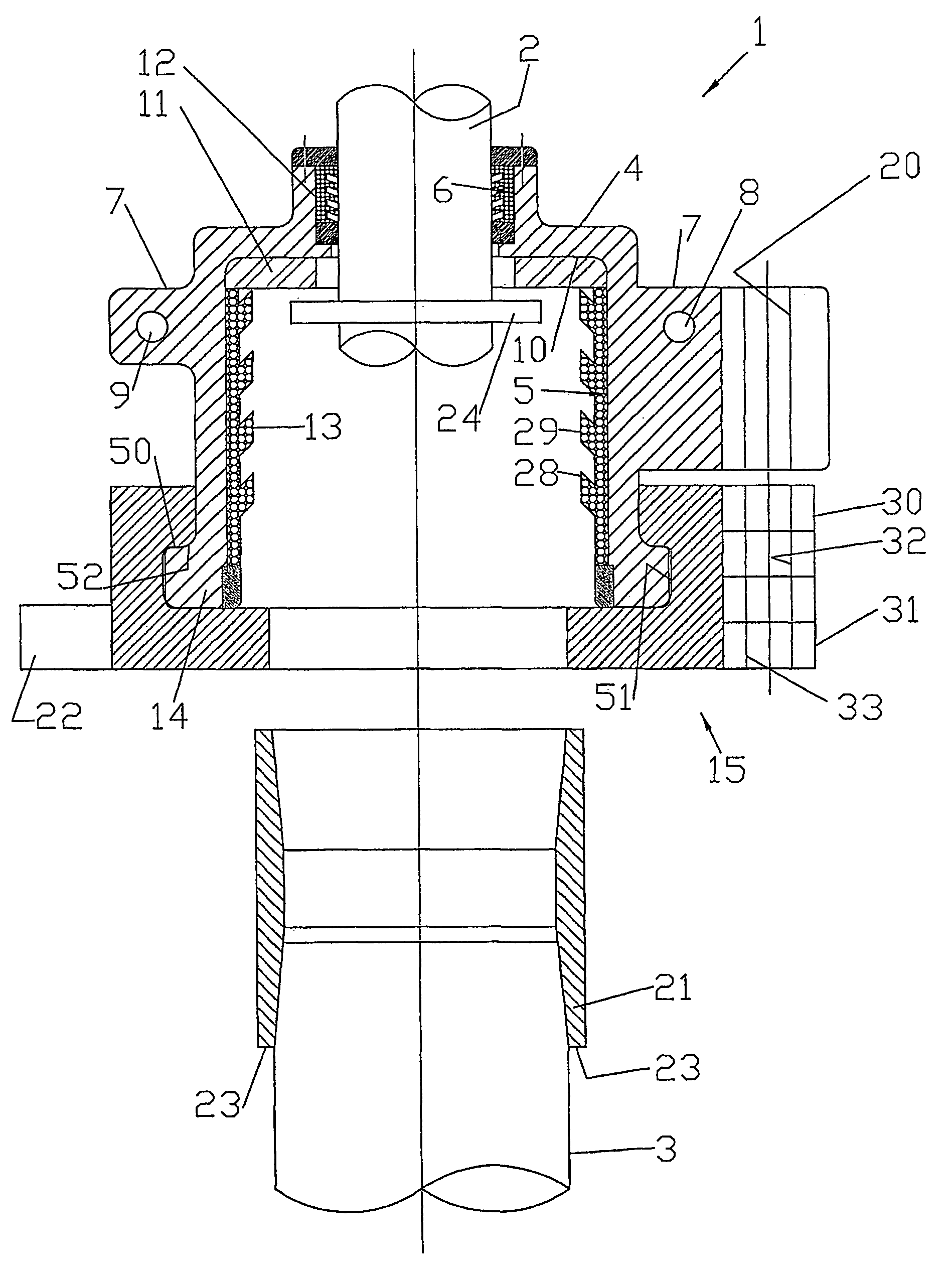
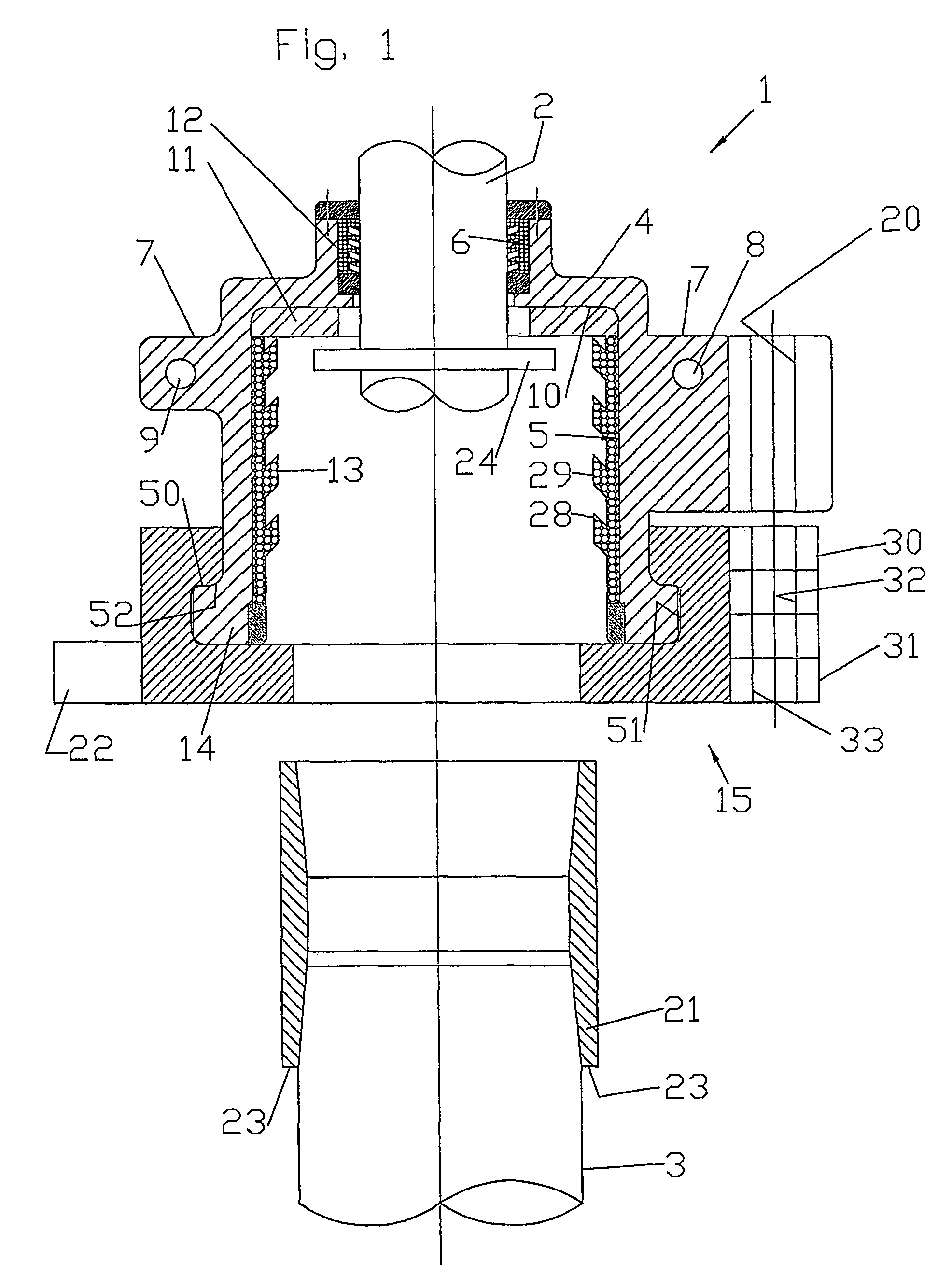
[0085]Referring to FIG. 1, the top circulating head is designated by numeral 1, and is used to couple a slick joint 2 with a bore hole casing 3.

[0086]The assembly 1 comprises a main body portion 4 having a large cylindrical bore 5, a small cylindrical bore 6 and a flange portion 7 with a pair of lifting lug holes 8, 9. Shoulder portion 10 between bores 5 and 6 supports a bumper ring 11 made of rubber or a similar material. Resilient (eg rubber) external seals 12 and 13 are mounted in the bores 5 and 6. A locking assembly 15 is mounted on the body portion 4 about an outwardly extending flange 14.

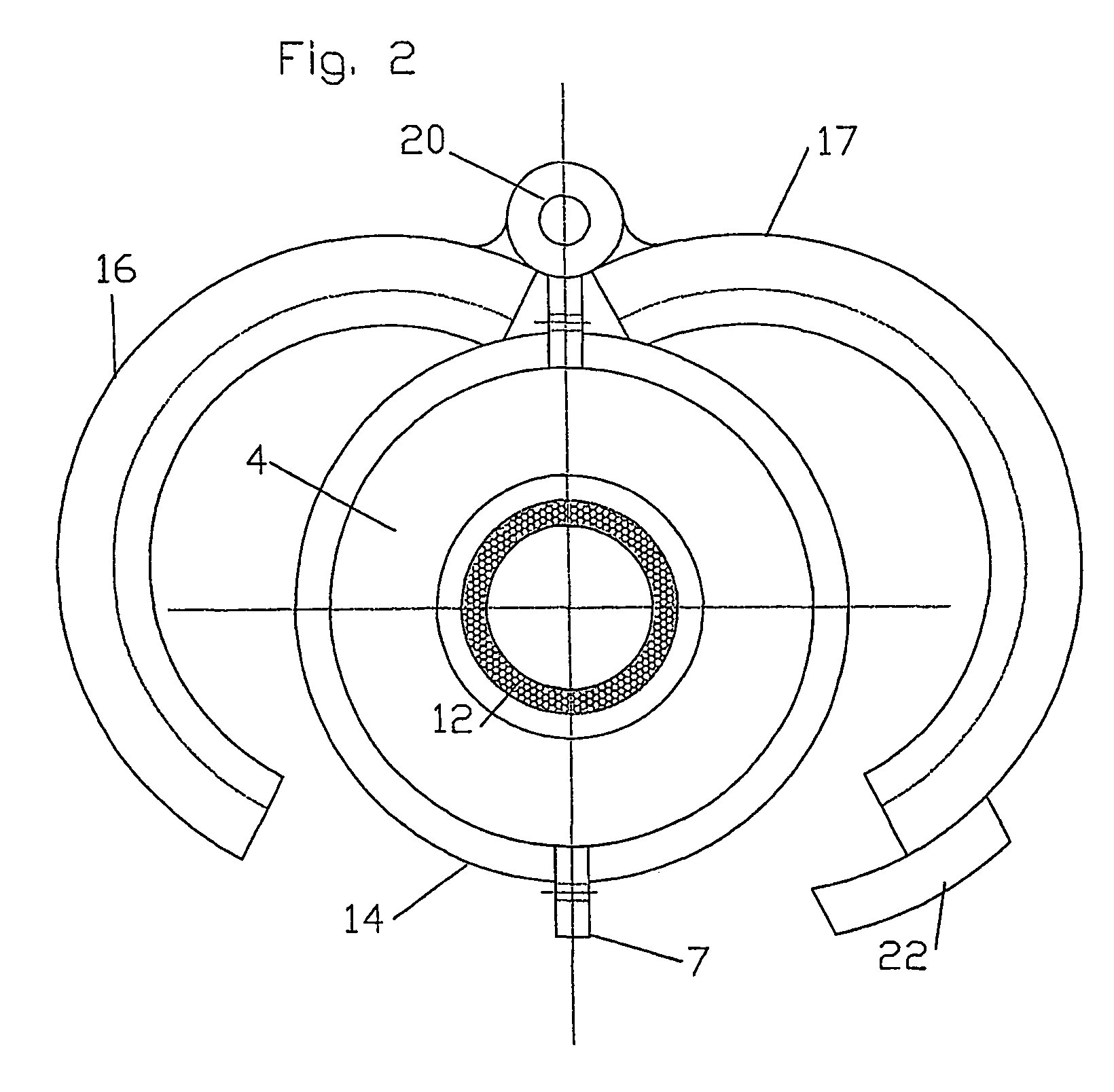
[0087]Referring to FIG. 2, the locking assembly 15 has a first semicircular door 16 and a second semicircular door 17. The doors 16, 17 each have respective hinge rings 30, 31 (FIG. 1) with bores 32, 33 aligned with a bore 20 in the flange 7. A pivot pin (not shown) passes through the bores 20, 32 and 33.

[0088]The main body portion 4 has an outwardly extending flange 14 which is received in a...


PUM


Abstract

An apparatus configured to a downhole tubular to a pump. The apparatus comprises: a body portion having a bore; a locking assembly comprising at least one locking member pivotally mounted to the body portion so as to permit the locking member to be pivoted between an open position in which the downhole tubular can be inserted into the bore of the body portion, and a closed position in which the locking member engages the downhole tubular so as to lock the downhole tubular in the bore of the body portion. Fixing means is provided for fixing the looking member in the closed position. A method of drilling a wellbore using a borehole casing.

Description

BACKGROUND OF THE INVENTION[0001]1. Field of the Invention[0002]The present invention relates to coupling apparatus for coupling a downhole tubular (such as a borehole casing) to a pump, conventionally known as a circulating head. The invention also relates to a method of pumping fluid into a downhole tubular, and to a method of drilling.[0003]2. Description of the Related Art[0004]A conventional circulating head is described by LeFleur et al in U.S. Pat. No. 5,282,653, U.S. Pat. No. 5,152,554 and U.S. Pat. No. 5,348,351. As described by LeFleur et al, when casing is being run in connection with the drilling of an oil or gas well, it sometimes becomes necessary to connect surface pumping equipment to circulate drilling fluid down the well. Typically, this need arises when a tight spot is encountered and drilling fluid is circulated down the well to run the casing past the tight spot and avoid the need for removing the casing and redrilling the hole.[0005]The circulating head describ...

Claims


Application Information

Patent Timeline
Patent Type & Authority Patents(United States)
IPC IPC(8): F16L21/00E21B17/02E21B19/06E21B19/07E21B19/16F16L21/06F16L37/00
CPCE21B19/06F16L37/002F16L21/06E21B33/05
Inventor NIVEN, DAVIDFERNANDES, DENNIS ROBERT MARIO
Owner WEATHERFORD TECH HLDG LLC
Why Eureka
Try Eureka