Electric compressor

a technology of electric compressor and electric motor, which is applied in the direction of positive displacement liquid engine, piston pump, liquid fuel engine, etc., can solve the problems of increasing the size and weight unnecessary radiating member, and inconvenient assembly of the electric compressor, so as to reduce the cost of the compressor and simplify the structure. , the effect of reducing the cos

Inactive Publication Date: 2006-12-12
PANASONIC CORP
View PDF4 Cites 20 Cited by
  • Summary
  • Abstract
  • Description
  • Claims
  • Application Information

AI Technical Summary

Benefits of technology

[0009]With this structure, the motor-driving circuit can be disposed in the axial direction without interposing the suction chamber between the motor-driving circuit and the discharge chamber. Therefore, the mountability of the compressor on a vehicle can be enhanced without increasing the size of the compressor.
[0018]According to the present invention, the suction chamber and the discharge chamber are formed substantially laterally, and the suction chamber is disposed on the opposite side from the internal combustion engine. With this structure, there is effect that the thermal influence from the internal combustion engine on the heat generating part of the motor-driving circuit can be avoided.

Problems solved by technology

Thus, a radiating member is unnecessary unlike the conventional technique.
However, the conventional structure has a problem that the electric compressor integrally provided with the inverter which drives the electric motor has such an outer shape that the unit housing radially projects from the outer peripheral surface of the substantially cylindrical machine body, the outer shape is distort, and the mountability of the electric compressor on a vehicle is inferior.
The inverter can be disposed in the axial direction, but since the discharge member is formed on a shaft end of the inverter on the side of the compression mechanism, in order to cool a heat-generating part of the inverter, it is necessary to interpose a suction chamber for cooling the heat-generating part between the inverter and the discharge chamber, or to provide some type of radiating member, and this increases the compressor in size and weight.

Method used


Image

  • Electric compressor
  • Electric compressor
  • Electric compressor

Examples


Embodiment Construction

[0022]An embodiment of the present invention will be explained with reference to the drawings. The invention is not limited by the embodiment.

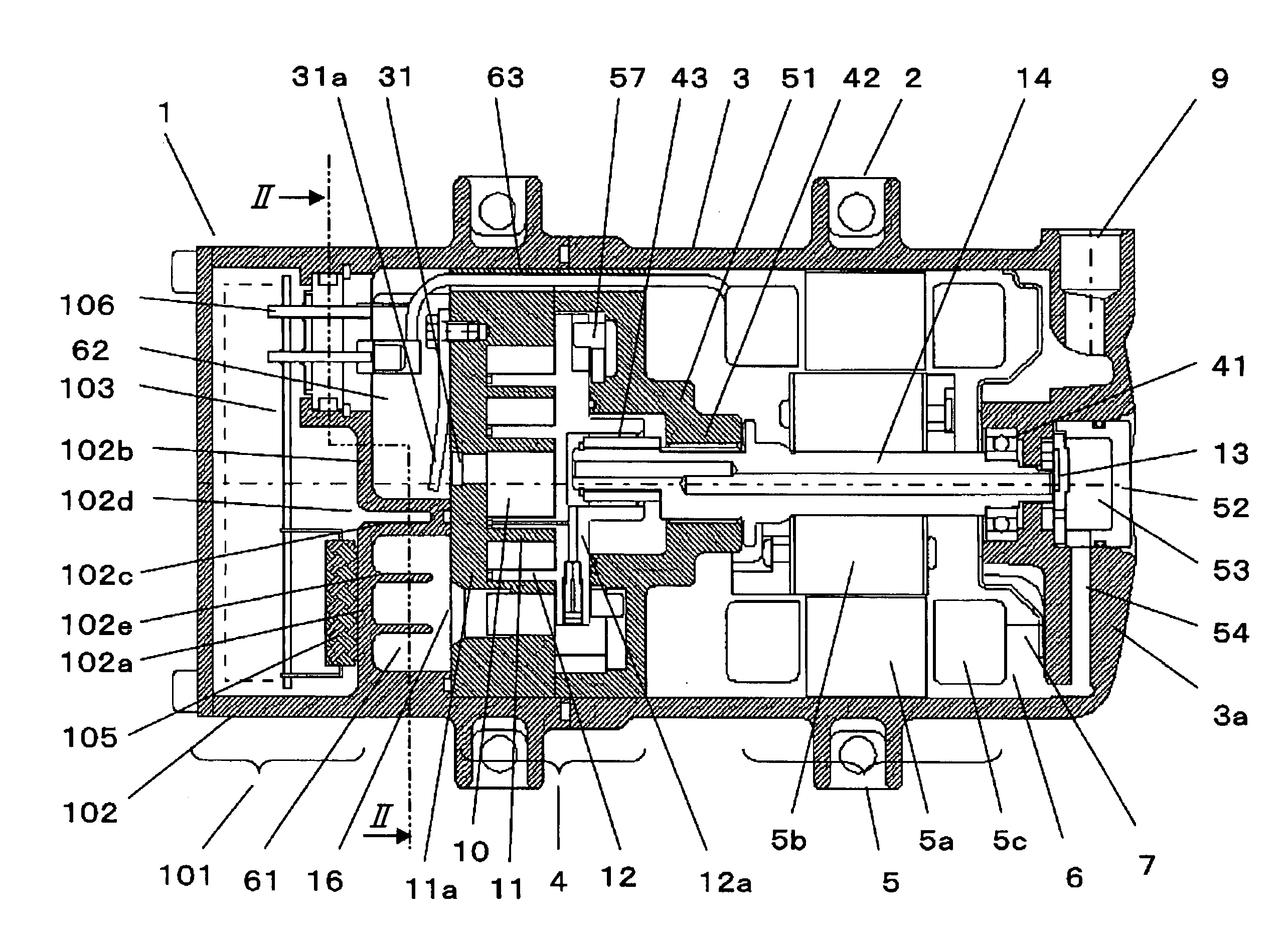
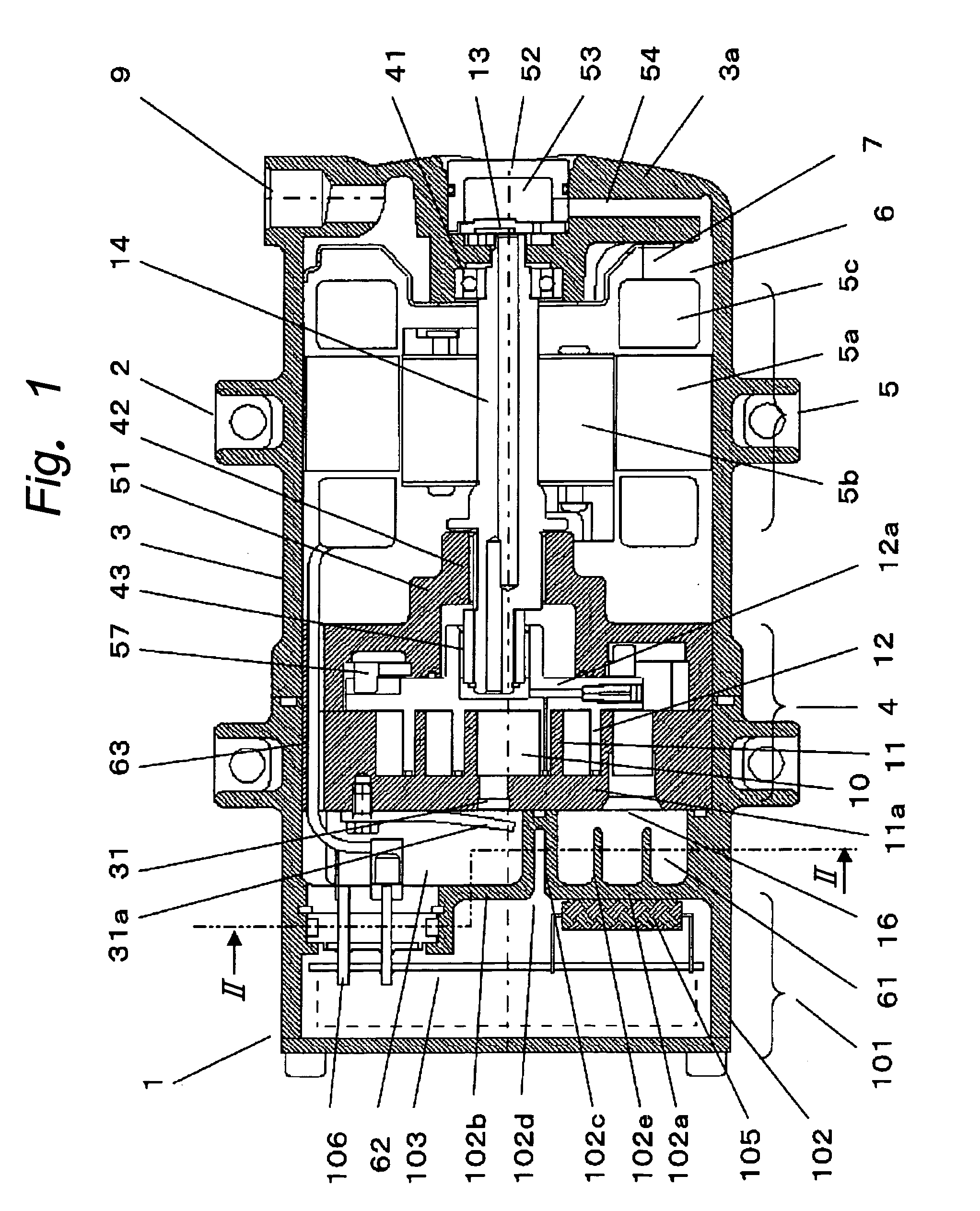
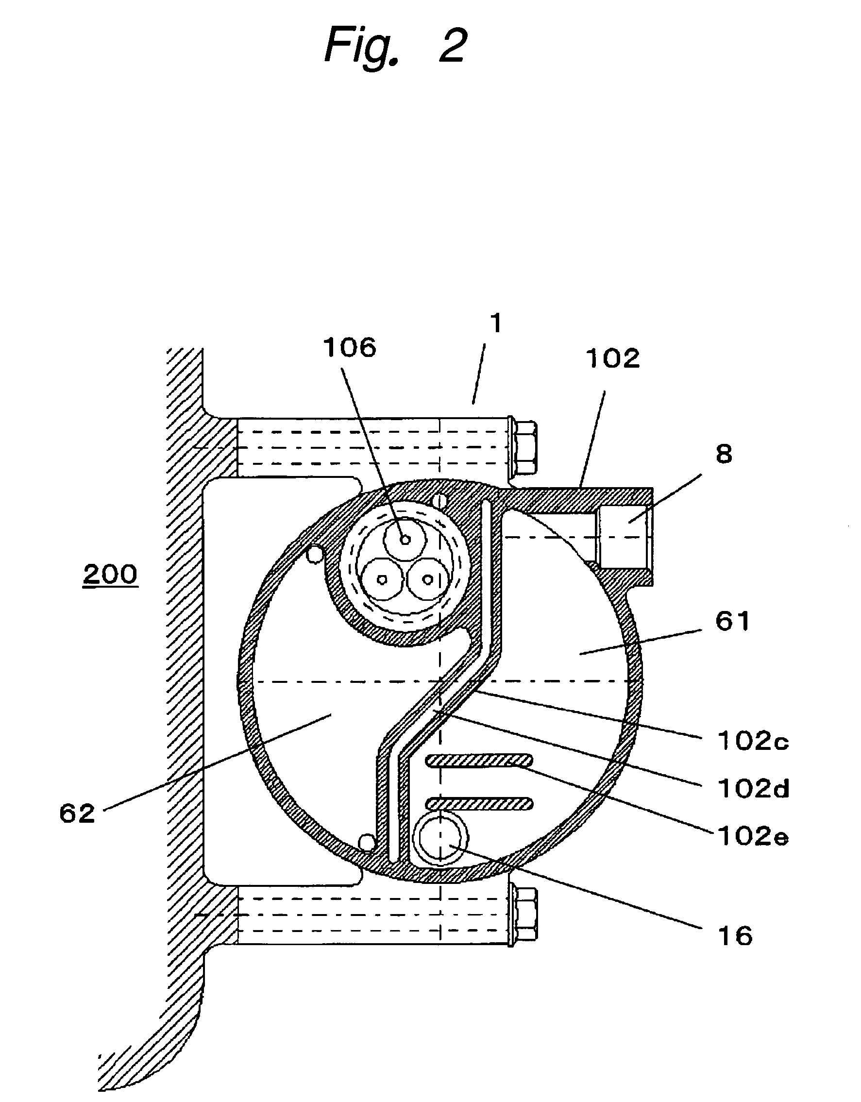
[0023]FIG. 1 is a sectional view of an electric compressor according to an embodiment of the present invention, and FIG. 2 is a sectional view taken along the line A—A in FIG. 1.

[0024]FIGS. 1 and 2 show one example of a lateral type electric compressor 1 which is disposed laterally on a side surface of an internal combustion engine 200 of a vehicle by mounting legs 2. The electric compressor 1 has a body casing 3 in which a compression mechanism 4 and a motor 5 for driving the compression mechanism 4 are accommodated. The electric compressor 1 also includes a liquid reservoir 6 in which liquid used for lubricating various sliding portions including the compression mechanism 4 is stored. The motor 5 is driven by a motor-driving circuit 101. A refrigerant used here is a gas refrigerant. Liquid such as lubricant oil 7 is used for lubricating the ...


PUM


Abstract

It is an object of the present invention to provide an electric compressor capable of enhancing the mountability with respect to a vehicle without increasing the compressor in size when the electric compressor and a motor-driving circuit which drives a motor of the electric compressor are integrally formed together. A suction chamber 61 which is in communication with a fixed panel suction port 16 provided in a fixed scroll 11 from a suction port 8 provided in a sub-casing 102, and a discharge chamber 62 which is in communication with a communication passage 63 from a fixed panel discharge port 31 provided in the fixed scroll 11 are disposed on the same plane in a radial direction of a compressor, and the motor-driving circuit 101 is disposed in an axial direction of the compressor so that an IPM 105 which is a heat generating part of the circuit substrate 103 can be brought into tight contact with the suction chamber 61.

Description

TECHNICAL FIELD[0001]The present invention relates to an electric compressor integrally provided with a motor-driving circuit, and more particularly, to a vehicle-mounted electric compressor.BACKGROUND TECHNIQUE[0002]In a conventional electric compressor of this kind, a motor-driving circuit is disposed on a body casing in which a compression mechanism and a motor are accommodated (e.g., see patent document 1).[0003]FIG. 3 is a sectional view of a conventional scroll compressor described in the patent document 1. In FIG. 3, an inverter 60 which controls an electric motor is mounted on a radially outer upper surface of a casing 7. The inverter 60 comprises a switching element 62. Among constituent elements of the inverter 60, the switching element 62 generates higher heat. The switching element 62 is supported such that the switching element 62 is pasted on an outer peripheral surface of a cylindrical body 63 in a unit housing 70 in which the inverter 60 is accommodated. The cylindri...

Claims


Application Information

Patent Timeline
Patent Type & Authority Patents(United States)
IPC IPC(8): F04B17/03F04B39/06F04B17/00F04B39/00F04C18/02F04C29/00F04C29/04
CPCF04B35/04F04B39/06F04C23/008F04C29/047F04C29/12F04C18/0215F04C2240/30F04C2240/808
Inventor OGAWA, NOBUAKIMAKINO, MASAHIKOFUJIWARA, YUKIHIRO
Owner PANASONIC CORP
Why Eureka
Try Eureka