Electrical connection device provided with at least one tubular end contact

a technology of electrical connection device and tubular end contact, which is applied in the direction of one-pole connection, coupling device connection, securing/insulating coupling contact member, etc., can solve the problems of difficult test, inability to connect plugs with sockets, and difficulty in satisfying test results

Active Publication Date: 2006-12-12
MARECHAL ELECTRIC
View PDF14 Cites 32 Cited by
  • Summary
  • Abstract
  • Description
  • Claims
  • Application Information

AI Technical Summary

Benefits of technology

[0018]Tubular contacts also make it possible to couple elements without imposing any particular angular orientation on the plug and the socket, which is very advantageous, particularly when using thick cables since any twisting is avoided.
[0019]Finally, tubular contacts also make it possible to release inside space within each contact that can advantageously be used, e.g. for receiving pilot contacts.

Problems solved by technology

Such connection devices present numerous problems for solving as a function of their applications, and in particular safety problems.
Testing consists in not being able to make contact between the standardized test finger and the live parts of the appliance under test while attempting to insert the test finger in all possible positions, said test being particularly difficult to satisfy when high-current electricity is involved.
In addition, it is also clear that a plug must not be capable of coupling with a socket unless they are mutually electrically compatible so that the currents and / or voltages and / or electrical power levels correspond between the two connection elements.
For this purpose, it is desired to use mechanical means to prevent two connection elements that are mutually electrically incompatible being coupled together, with this being made more difficult by the fact that the component parts of such elements are standardized, in particular for reasons of cost.
Unfortunately, conventional devices, and in particular single-pole appliance couplers, often do not have sufficient space for receiving pilot contacts.

Method used


Image

  • Electrical connection device provided with at least one tubular end contact
  • Electrical connection device provided with at least one tubular end contact
  • Electrical connection device provided with at least one tubular end contact

Examples


Embodiment Construction

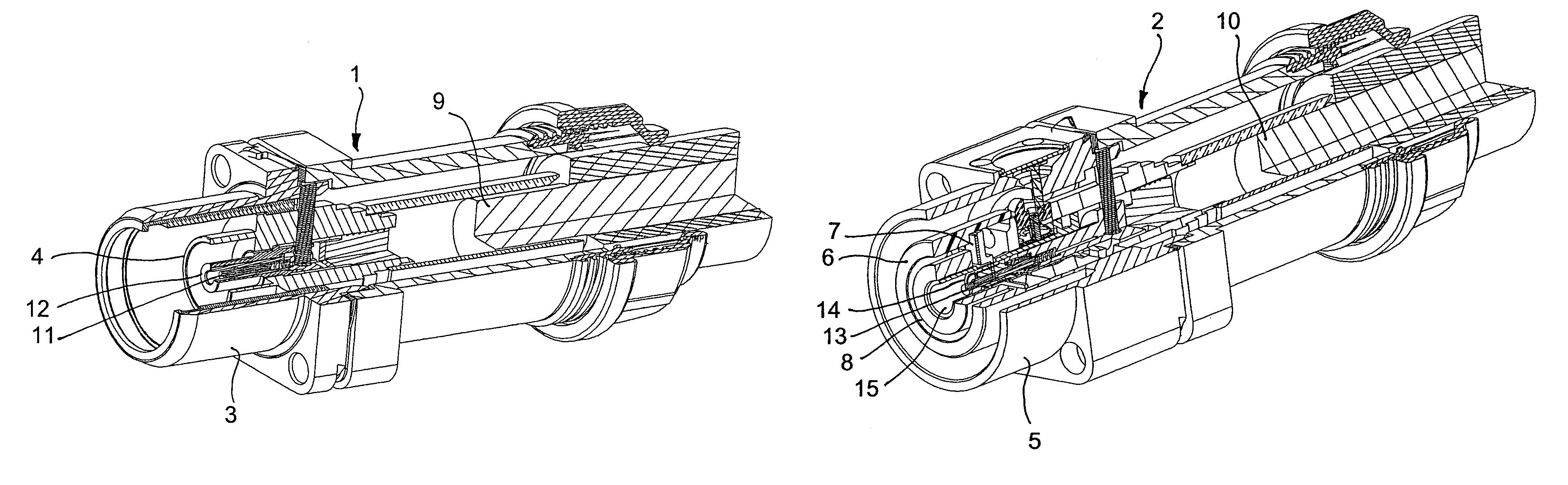
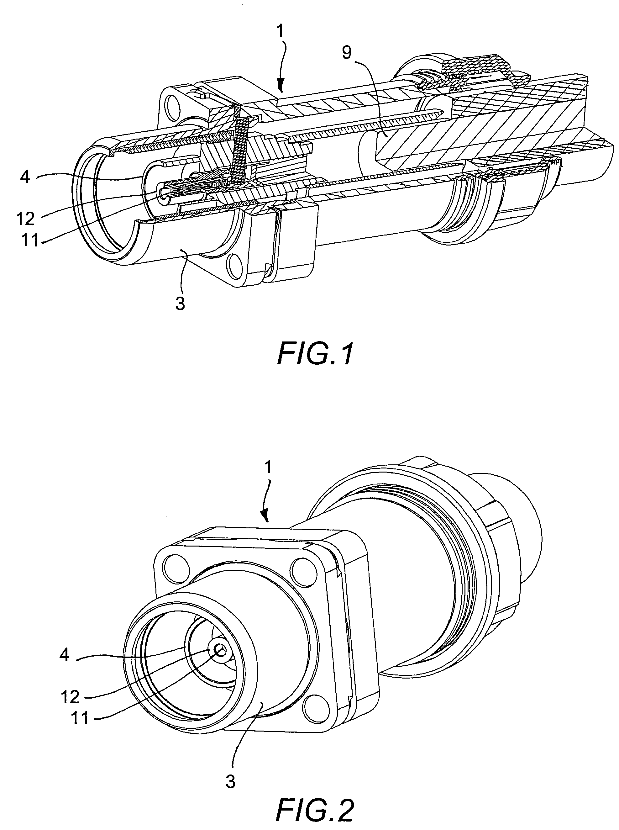
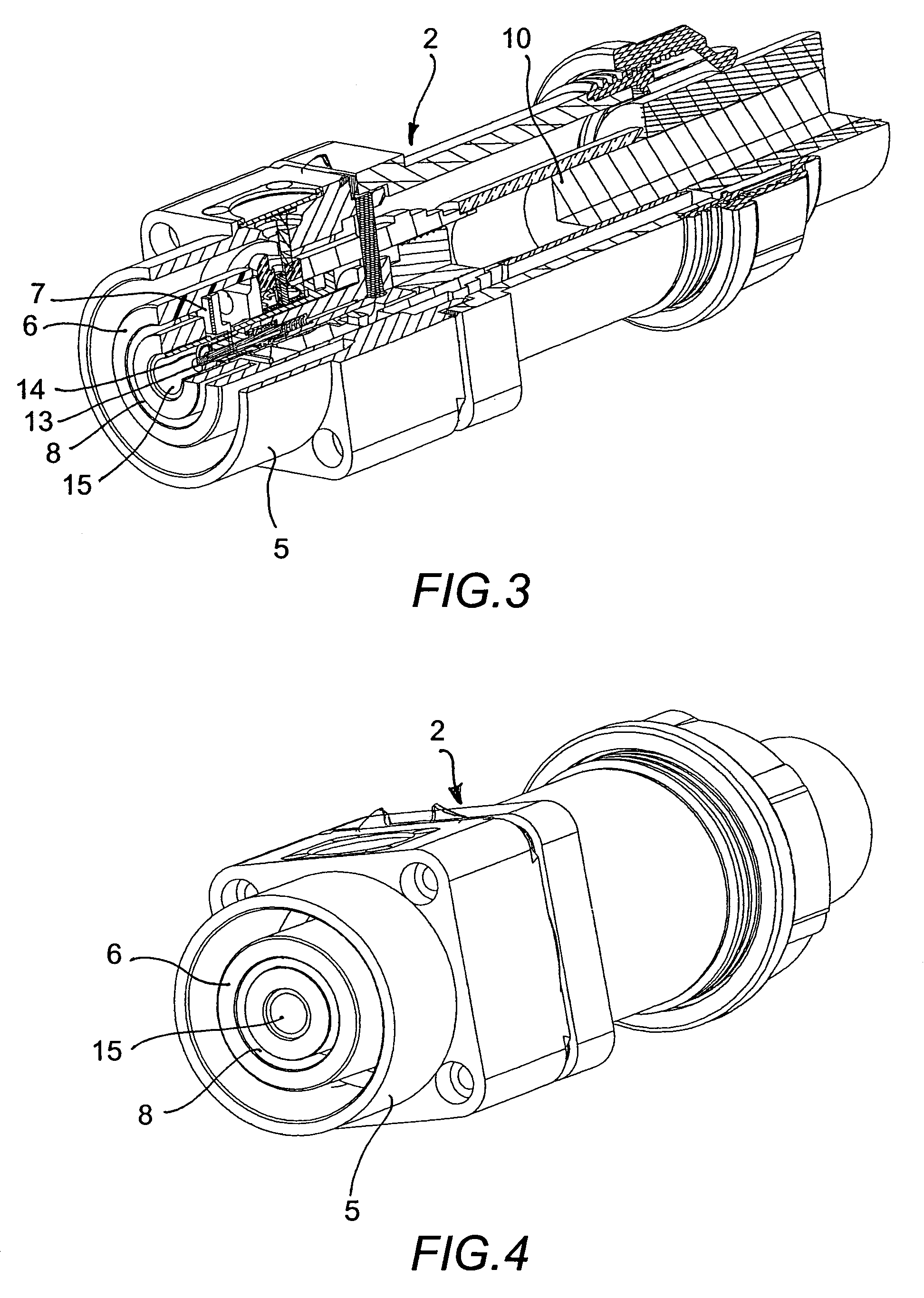
[0032]By way of example, and because the invention is particularly well adapted to devices of this type, the embodiment shown is a single-pole connection device, i.e. each of the plug 1 and the socket 2 constituting the device includes only a single power contact (live, neutral, ground, . . . ).

[0033]In addition, there is shown herein a device of the cable coupler type, i.e. having a socket and a plug that are both portable, the socket constituting a “connector” in the terminology of international standards. The socket and the plug of the cable coupler are for coupling together by various mechanical means so as to establish an electrical connection between their contacts.

[0034]It is thus for reasons of simplicity that the words “socket” and “plug” are used, however it is clear that the socket could be fixed to constitute a socket-outlet in the terminology of international standards, or on the contrary, the plug could be fixed and constitute an appliance inlet according to said stand...


PUM


Abstract

An electrical connection device including a socket having at least one axial pressure contact arranged in insulation and at least one annular groove. A plug has at least one tubular contact that is coaxial about a direction of coupling of the plug with the socket. The at least one tubular contact includes a leading end having an end surface. The at least one tubular contact is structured and arranged to co-operate with the at least one axial pressure contact of the socket. The at least one annular groove opens out axially and is structured and arranged to receive therein the at least one tubular contact. At least a portion of the end face of the leading end of the at least one tubular contact presses against the at least one axial pressure contact when the at least one tubular contact is positioned in the at least one annular groove and when the plug is coupled with the socket.

Description

CROSS-REFERENCE TO RELATED APPLICATIONS[0001]The present application claims priority under 35 U.S.C. §119 of French Patent Application No. 0306394, filed on May 27, 2003, the disclosure of which is expressly incorporated by reference herein in its entirety.BACKGROUND OF THE INVENTION[0002]1. Field of the Invention[0003]The invention relates to an electrical connection device constituted by an active socket and a plug provided with at least one contact that is designed to co-operate with an opposing contact of the socket arranged in insulation, which insulation is provided with at least one passage for introducing said contact of the plug while coupling the plug with the socket.[0004]The connection devices to which the invention relates are in particular plug and socket-outlets, cable couplers, and appliance couplers.[0005]2. Discussion of Background Information[0006]Such connection devices present numerous problems for solving as a function of their applications, and in particular s...

Claims


Application Information

Patent Timeline
Patent Type & Authority Patents(United States)
IPC IPC(8): H01R24/00H01R13/40H01R4/18H01R13/44H01R13/64H01R24/02
CPCH01R13/44H01R23/26H01R24/20H01R24/38H01R4/18H01R2101/00H01R2103/00
Inventor MARECHAL, GILLESCRESTIN, JOSEPHGILET, FABRICE
Owner MARECHAL ELECTRIC
Why Eureka
Try Eureka