Ignition wire with grafted coating and method of making

a technology of ignition wire and coating, which is applied in the direction of insulated conductors, cables, conductors, etc., can solve the problems of high temperature, abrasion, and the construction of kawaguchi cannot be applied for the protection of cosmetic or decorative materials or enhancement, and achieve the effect of enhancing the resistance to abrasion of the insulating jacket without deteriorating the electrical or mechanical performance characteristics

Active Publication Date: 2006-12-12
STANDARD MOTOR PROD INC
View PDF23 Cites 14 Cited by
  • Summary
  • Abstract
  • Description
  • Claims
  • Application Information

AI Technical Summary

Benefits of technology

[0013]In one aspect, the present invention is an ignition wire having a coating layer which is chemically grafted and bonded to the exterior surface of an insulating jacket. Still further, the coating layer may be transparent and afford advantages for use in providing a clear coat on the outer surface of the insulating jacket layer as well as use in conjunction with a cosmetic layer applied to this surface. The coating layer is adapted to provide improved resistance to abrasion to the insulating jacket. The coating also provides an aesthetically pleasing surface finish, such as a clear-coat finish on the exterior surface of the ignition wire.
[0016]In a fourth aspect, the coating layer provides enhanced resistance to abrasion of the insulating jacket without deteriorating the electrical or mechanical performance characteristics of either the insulation layer or the insulating jacket.

Problems solved by technology

Being located on the outer surface, such materials are subject to high temperatures, abrasion from dirt and other under-hood sources of abrasion, mechanical stress, chemicals and other agents which promote their degradation.
It is believed that the construction of Kawaguchi would not be applicable for the protection of the cosmetic or decorative materials or enhancing the abrasion resistance of the jacket because it is applied over a release coating and is designed to be readily removed from the outer surface of the wire jacket.

Method used


Image

  • Ignition wire with grafted coating and method of making
  • Ignition wire with grafted coating and method of making

Examples


example 1

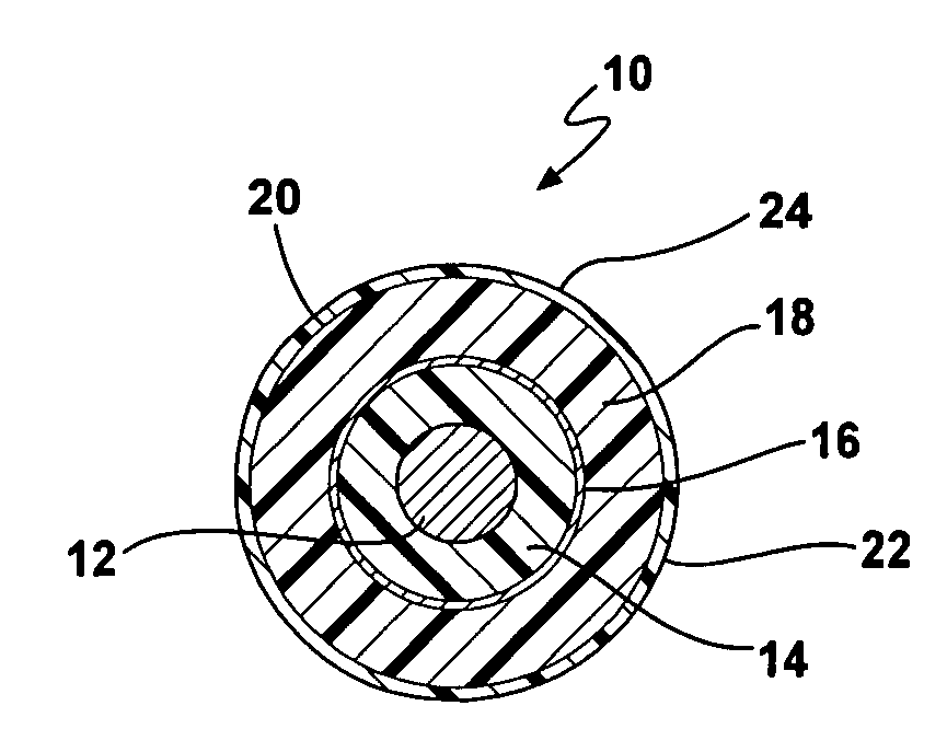
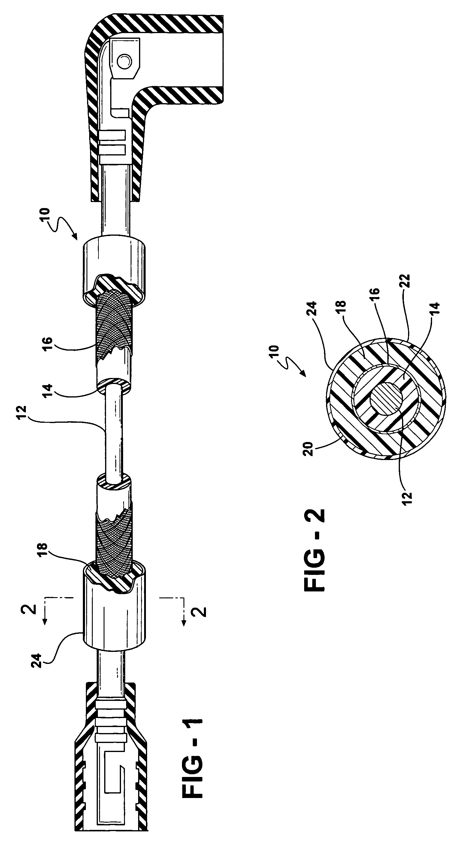
[0029]A preferred transparent coating layer 24 may be made from a coating material composition which includes between 35 and 45 parts by weight of a silicone prepolymer, less than 1 part by weight of a silane coupling agent, less than 1 part by weight of a catalyst, less than 1 part by weight of a graft initiator and the balance a reactive solvent.

[0030]The silicone prepolymer is preferably an RTV silicone that is adapted upon curing to provide a silicone polymer coating layer 24. The coupling agent is preferably a silane coupling a gent, and more preferably an amino-functional silane coupling agent. The catalyst is preferably operative to promote grafting by polymerization of the silicone polymer coating 24 to the outer surface of insulating jacket layer 18. The graft initiator is operative to prepare the outer surface of the insulating jacket layer to receive by grafting a coating layer comprising the silicone prepolymer and said coupling agent. It is believed that the graft initi...


PUM

PropertyMeasurementUnit
diameteraaaaaaaaaa
diameteraaaaaaaaaa
thicknessaaaaaaaaaa

Abstract

An ignition wire includes a conductive core, an insulation layer surrounding the core, an insulating jacket surrounding the insulation layer and a coating layer which is grafted and bonded to at least a portion of an exterior surface of the insulating jacket. The coating layer and insulating jacket are preferably formed of silicone materials. The coating layer is operative to provide enhanced resistance to heat and abrasion, as well as other benefits to the exterior surface of the insulating jacket. The coating layer may be transparent and provide an aesthetically pleasing clear coat, or may be tinted or colored to produce various other cosmetic or decorative characteristics to the outer surface of the ignition wire. The coating layer provides these enhanced protections without the diminishing electrical or mechanical performance properties of either the insulation layer or the insulating jacket. The coating layer is also adapted to provide protection to a cosmetic layer which may be applied to the exterior surface of the insulating jacket.

Description

CROSS-REFERENCES TO RELATED APPLICATIONS[0001]This patent application claims priority to U.S. Provisional Patent Application Ser. No. 60 / 585,125, filed Jul. 2, 2004, which is hereby incorporated herein by reference in its entirety.BACKGROUND OF THE INVENTION[0002]1. Field of the Invention[0003]The present invention relates generally to insulated electrical conductors and, in particular, to ignition wires for spark plugs and similar ignition devices.[0004]2. Related Art[0005]Ignition wires for spark plugs commonly include a conductive core, a conductor or semi-conductor coating layer, a release coating, an electrical insulation layer, a strengthening layer to provide enhanced tensile strength and an insulating outer sheath or jacket, and may also include various adhesive and other inner layers. The outer jacket also frequently includes a cosmetic or decorative layer or printed portion on its outer surface. The layers described above may be arranged in different combinations and order...

Claims


Application Information

Patent Timeline
Patent Type & Authority Patents(United States)
IPC IPC(8): H01B7/00
CPCH01B7/0063H01B7/365H01B7/18Y10T29/49123Y10T29/49117H01B3/46H01B3/47
Inventor HOPPER, BRADLEY T.
Owner STANDARD MOTOR PROD INC
Why Eureka
Try Eureka