Power supply device for electric discharge machining

a technology of power supply device and electric discharge, which is applied in the direction of electric variable regulation, instruments, manufacturing tools, etc., can solve the problems of difficult control of the charge voltage of the capacitor applied, low energy efficiency, and complicated control circuit of the switching element, so as to achieve the effect of removing energy loss and hardly producing energy loss

Inactive Publication Date: 2006-12-12
FANUC LTD
View PDF12 Cites 10 Cited by
  • Summary
  • Abstract
  • Description
  • Claims
  • Application Information

AI Technical Summary

Benefits of technology

[0012]The present invention provides a power supply device for electric discharge machining in which energy loss is hardly produced and a charge voltage of a capacitor is easily controlled.

Problems solved by technology

Hence, the energy efficiency is low.
Hence, it is difficult to control a charge voltage of the capacitor which is applied between the electrode and a workpiece.
In order to control the charge voltage of the capacitor, it is necessary to accurately set an ON-time of the switching element by estimating charges supplied from the inductor, so that a control circuit of the switching element is complicated.

Method used


Image

  • Power supply device for electric discharge machining
  • Power supply device for electric discharge machining
  • Power supply device for electric discharge machining

Examples


Embodiment Construction

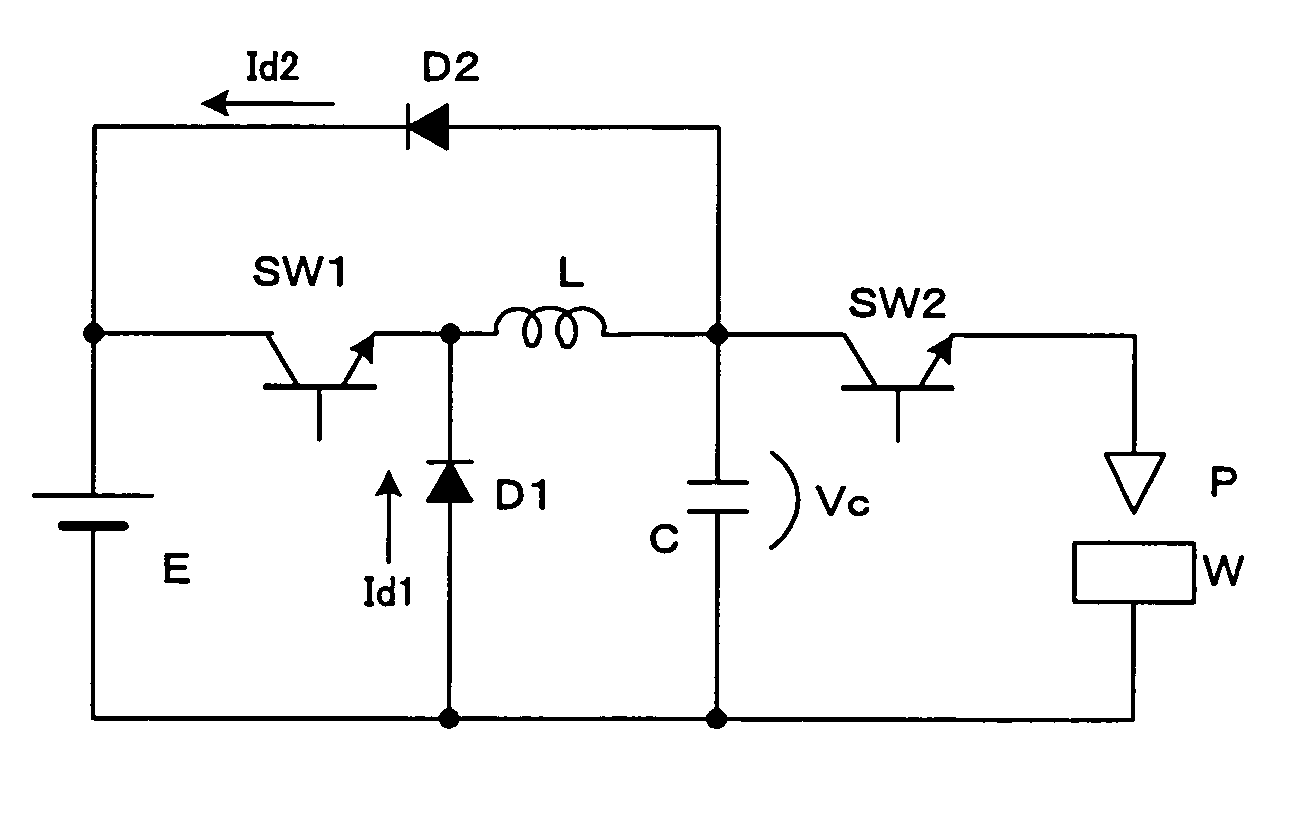
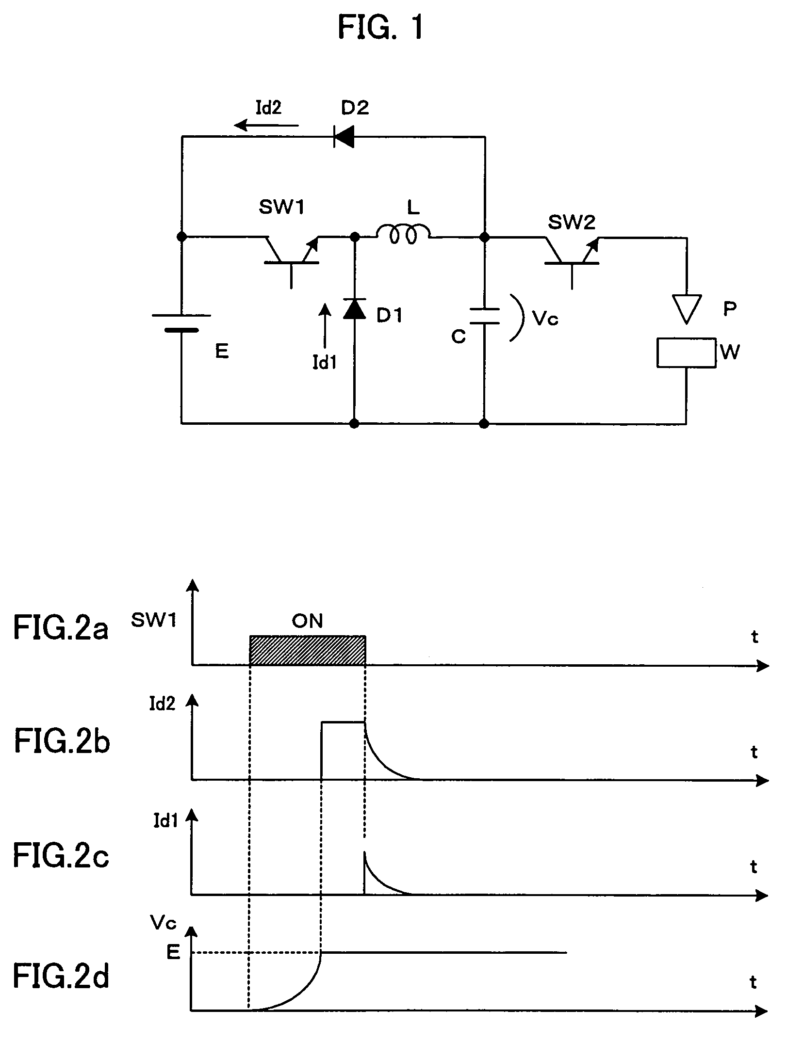
[0022]FIG. 1 shows a power supply device for electric discharge machining according to an embodiment of the present invention.

[0023]Direct-current power source E, a first switching element (transistor) SW1, an inductor L, a second switching element (transistor) SW2, an electrode P as one pole and a workpiece W as the other pole are connected in series. A capacitor C is connected between the second switching element (transistor) SW2 and the electrode P and workpiece W as the two poles to be in parallel. In other words, the capacitor C is connected in parallel with the series of the second switching element (transistor) SW2 and the electrode P and workpiece W as the two poles. Further, a first diode D1 is connected in a reverse direction between the direct-current power source E and the first switching element SW1 to be parallel with the series of the direct-current power source E and the first switching element SW1. As far as the structure described above is concerned, the present em...


PUM

PropertyMeasurementUnit
currentaaaaaaaaaa
electrical energyaaaaaaaaaa
electric energyaaaaaaaaaa

Abstract

An electric-discharge-machining power supply device in which energy loss is hardly produced and a charge voltage of a capacitor is easily controlled. When a switching element SW1 is turned on, a capacitor C is charged via an inductor L. When the voltage Vc of the charged capacitor exceeds the voltage of a direct-current power source E, a current is returned to the power source E via a diode D2. When the switching element SW1 is turned off, energy stored in the inductor L flows from the inductor L through the diode D2, the power source E and the diode D1, so that the voltage Vc of the capacitor C is kept at the power source voltage. When a switching element SW2 is turned on, the voltage of the capacitor is applied between an electrode and a workpiece.

Description

BACKGROUND OF THE INVENTION[0001]1. Field of the Invention[0002]The present invention relates to a power supply device for electric discharge machining, and in particular to a power supply device in which charging and discharging of a capacitor for storing electrical energy for the electric discharge machining is controlled by switching elements.[0003]2. Description of Related Art[0004]As means of improving a machining speed using a capacitor-type machining power supply device which charges a capacitor and applies the voltage of the charged capacitor between a workpiece and an electrode to cause electric discharge to perform machining, there is known a capacitor-type power supply device for electric discharge machining comprising switching elements for controlling the charging and discharging of the capacitor. FIG. 3 is an example of the capacitor-type power supply device for electric discharge machining in which the control of the charging and discharging is performed by switching ...

Claims


Application Information

Patent Timeline
Patent Type & Authority Patents(United States)
IPC IPC(8): B23H1/02G05F1/40B23H7/04
CPCB23H1/022B23H7/04B23H2300/20
Inventor MURAI, MASAOKAWAHARA, AKIYOSHI
Owner FANUC LTD
Why Eureka
Try Eureka