Videophone device

a technology of videophone and video display, which is applied in the direction of color television details, two-way working systems, television systems, etc., can solve the problems of unnatural image display, inability to remain viewers,

Inactive Publication Date: 2006-12-12
PANASONIC CORP
View PDF40 Cites 122 Cited by
  • Summary
  • Abstract
  • Description
  • Claims
  • Application Information

AI Technical Summary

Benefits of technology

[0029]In the video telephone apparatus according to the aspect (8), the use form of the video telephone apparatus is detected based on the orientation of the iii, that is, the orientation of the video telephone apparatus main unit to switch between the first receiver means and the second receiver means. Thus, the user can make proper conversation fit for the current situation.
[0033]In the video telephone apparatus according to the aspect (10), the use form of the video telephone apparatus is detected based on the orientation of the iii, that is, the orientation of the video telephone apparatus main unit to switch between the first transmitter means and the second transmitter means. Thus, the user can make proper conversation fit for the current situation.

Problems solved by technology

As a result, there occurred such a problem as viewers in the center among a plurality of viewers could view a crisp image but the remaining viewers could not.
Thus, problems arise that a picked-up image is transmitted to the distant party with the orientation of the image left unnatural and that the image is displayed in an unnatural orientation.

Method used


Image

  • Videophone device
  • Videophone device
  • Videophone device

Examples


first embodiment

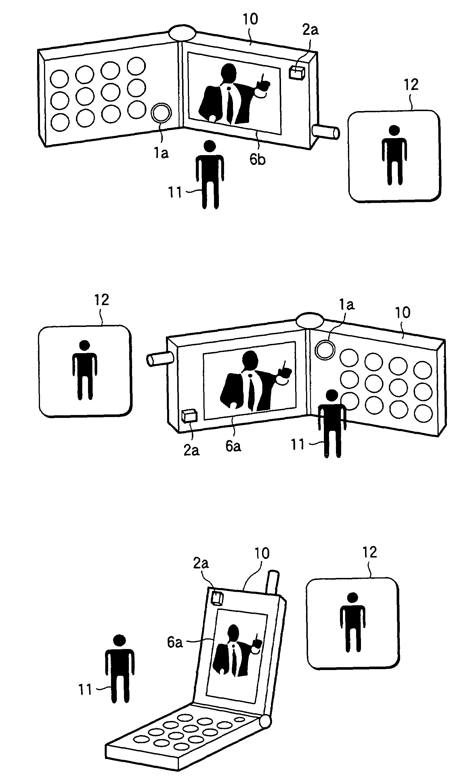
[0048]Video telephone apparatus according to the first embodiment can transmit and display a picked-up image and a received image in a normal state by rotating the picked-up image and the received image based on the vertical direction of iii, irrespective of the form of talking of the video telephone apparatus.

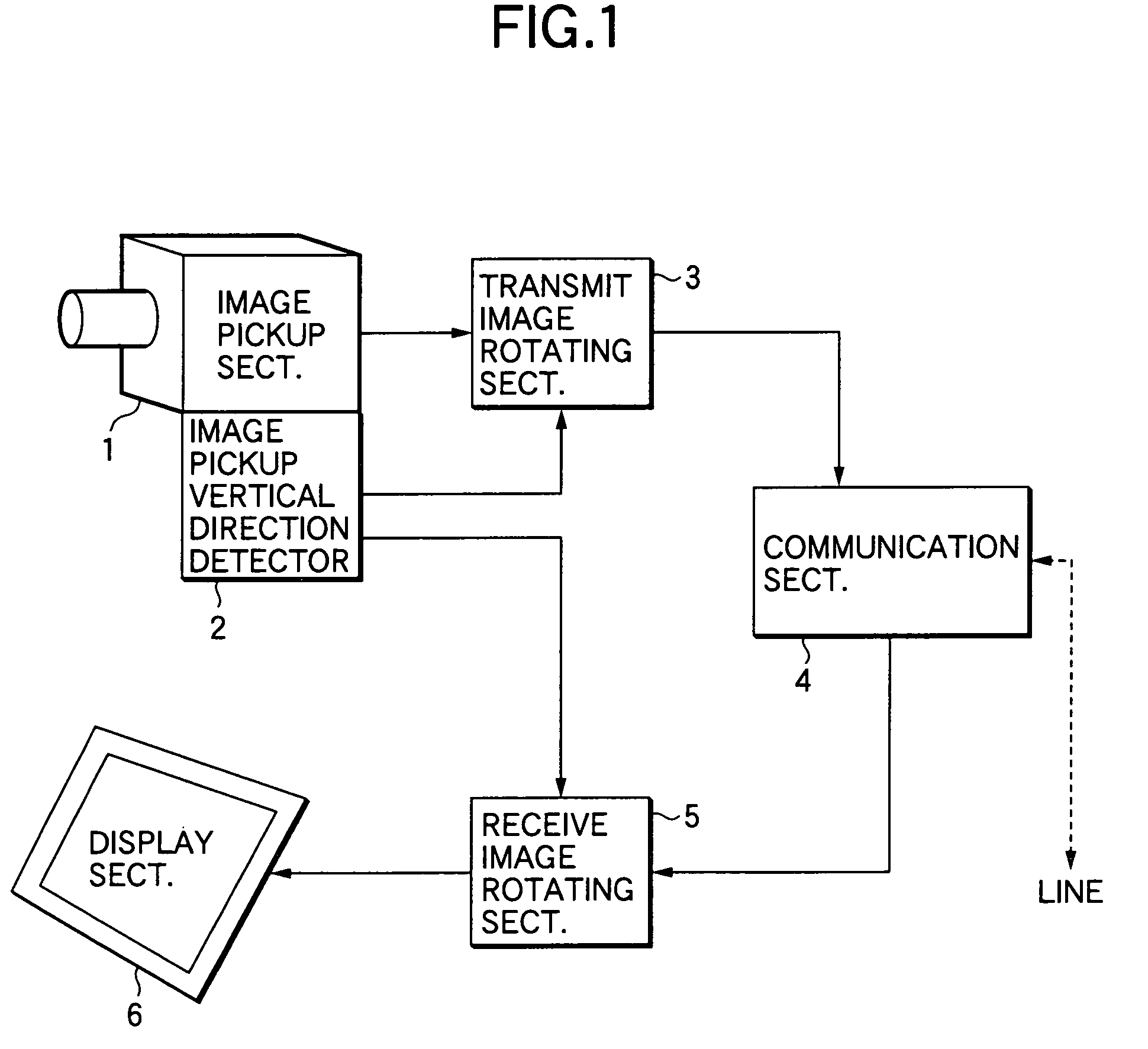
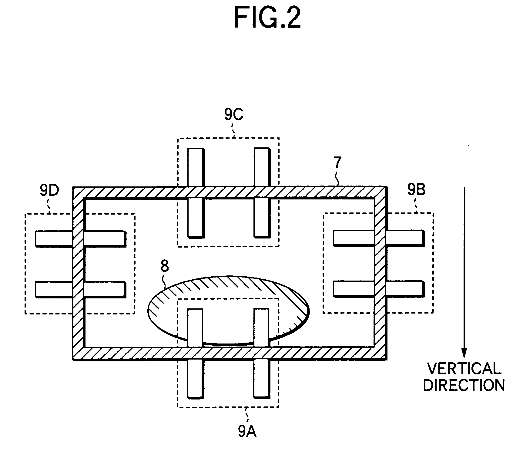
[0049]FIG. 1 is a block diagram showing the configuration of video telephone apparatus according to the first embodiment of the invention. FIG. 2 is a longitudinal section showing a configuration of the image pick-up vertical direction detector. FIG. 3 is a perspective view showing a positioning example of video telephone apparatus main unit 10. FIG. 4 is a perspective view showing a positioning example of video telephone apparatus main unit 10 having a detachable image pick-up section 1b.

[0050]As shown in FIG. 1, video telephone apparatus according to the first embodiment has an image pick-up section 1 corresponding to image pick-up means for picking up the image of an objec...

second embodiment

[0075]Video telephone apparatus according to the second embodiment of the invention can transmit and display a picked-up image and a displayed image in a normal state by rotating the picked-up image and the displayed image based on the vertical direction of display means, irrespective of the form of talking of the video telephone apparatus.

[0076]FIG. 5 is a block diagram showing the configuration of video telephone apparatus according to the second embodiment of the invention. FIG. 6 is a perspective view showing a configuration of video telephone apparatus main unit having a detachable display 6c. Description of the components in the figures that serve to act the same as the means included in the first embodiment is omitted.

[0077]As shown in FIG. 5, video telephone apparatus according to the second embodiment has an image pick-up section 1 for picking up the image of an object and generating a picture signal according to the image of the object, a transmit image rotating section 3 ...

third embodiment

[0091]Video telephone apparatus according to the third embodiment can transmit and display a picked-up image and a received image in a normal state by rotating the picked-up image and the received image based on the vertical direction of iii, irrespective of the form of talking of the video telephone apparatus. Further, the video telephone apparatus according to the third embodiment can generate voice data to transmit to the distant party via communication means and voice data received from the distant party via communication means according to the form of talking of the video telephone apparatus.

[0092]FIG. 7 is a block diagram showing the configuration of video telephone apparatus according to the third embodiment of the invention. Components in the figure that serve to act the same as the means included in the first and second embodiments are given the same numbers and the corresponding description is omitted.

[0093]As shown in FIG. 7, video telephone apparatus according to the thi...


PUM


Abstract

Providing video telephone apparatus where the orientation of a picked-up image or a received image can be changed according to the orientation of the image pick-up section or the display, thus allowing transmission or display of a proper image at any time.In video telephone apparatus according to the invention, an image pick-up section outputs the image data on the target object to a transmit image rotating section. The transmit image rotating section performs rotation processing on a picked-up image so that the upper side of an image pick-up section in the vertical direction coincides with the upper side of an image to transmit to the distant party, based on the orientation of the image pick-up section detected by an image pick-up vertical direction detector. A picture signal received from the distant party is demodulated and output to a receive image rotating section. The receive image rotating section performs rotation processing so that the upper side of the receive image is at the upper side of a display in the vertical direction, based on the vertical direction of the image pick-up section of the an image pick-up vertical direction detector, that is, the orientation of the display.

Description

TECHNICAL FIELD[0001]The present invention relates to video telephone apparatus that transmits / receives image information and audio information.BACKGROUND OF THE INVENTION[0002]In recent years, digital lines that can transmit / receive audio information and video information via a multichannel system such as the ISDN (integrated services digital network) have been in commercial use. In line with such a trend, the video telephone apparatus has come into widespread use. The video telephone apparatus is composed of at least transmitter means for transmitting images picket up via image pick-up means and associated voice data from the local party or user of the video telephone apparatus to the distant party, receiver means for receiving images and associated voice data from the distant party, and display means for displaying the images on a display and so on. While a liquid crystal panel is used as the display means based on the advantages of lightweight and low-profile design, the liquid ...

Claims


Application Information

Patent Timeline
Patent Type & Authority Patents(United States)
IPC IPC(8): H04N7/14H04M11/02H04N5/225
CPCH04N5/2251H04N7/142H04N2007/145H04N23/50H04N23/63
Inventor MITSUI, KENICHITODA, TOSHIYUKI
Owner PANASONIC CORP
Why Eureka
Try Eureka