Laser noise cancel circuit and optical disk device
a noise reduction circuit and optical disk technology, applied in the field of laser noise reduction circuit and optical disk device, can solve the problems of difficult control, difficult to obtain a sufficient depression effect on laser noise, and adverse effects on reproduced signals, and achieve high noise reduction effect and high accuracy.
- Summary
- Abstract
- Description
- Claims
- Application Information
AI Technical Summary
Benefits of technology
Problems solved by technology
Method used
Image
Examples
first embodiment
[First Embodiment]
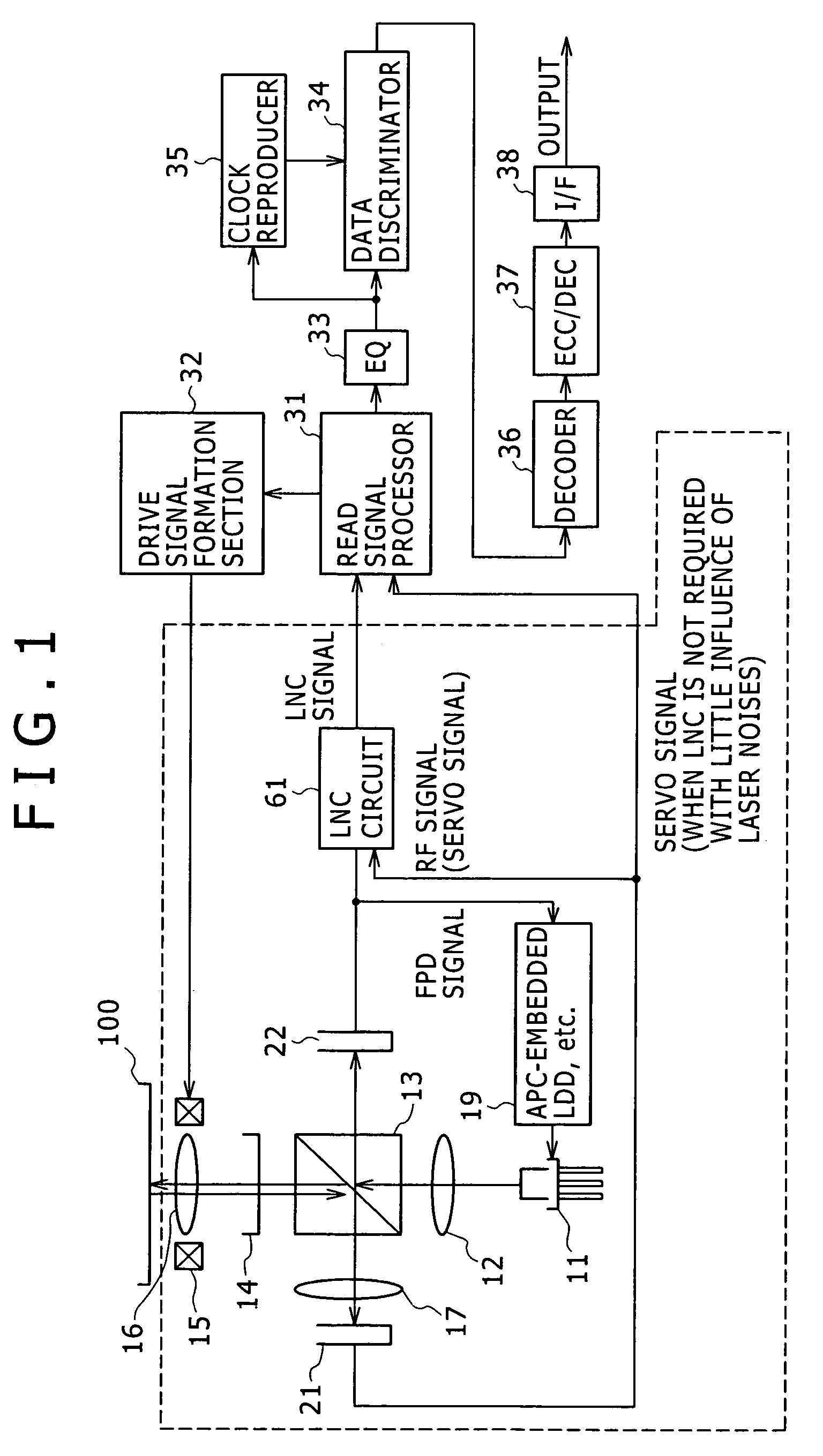
[0031]FIG. 1 is a block diagram explaining an optical disk device using a laser noise cancel circuit according to this first embodiment.
[0032]The optical disk device includes a light pickup section 1, a read signal processor 31, a drive signal formation section 32, an equalizer 33, a data discriminator 34, a clock reproducer 35, a decoder 36, an ECC (Error Correcting Code) decoder 37, and an interface section 38.
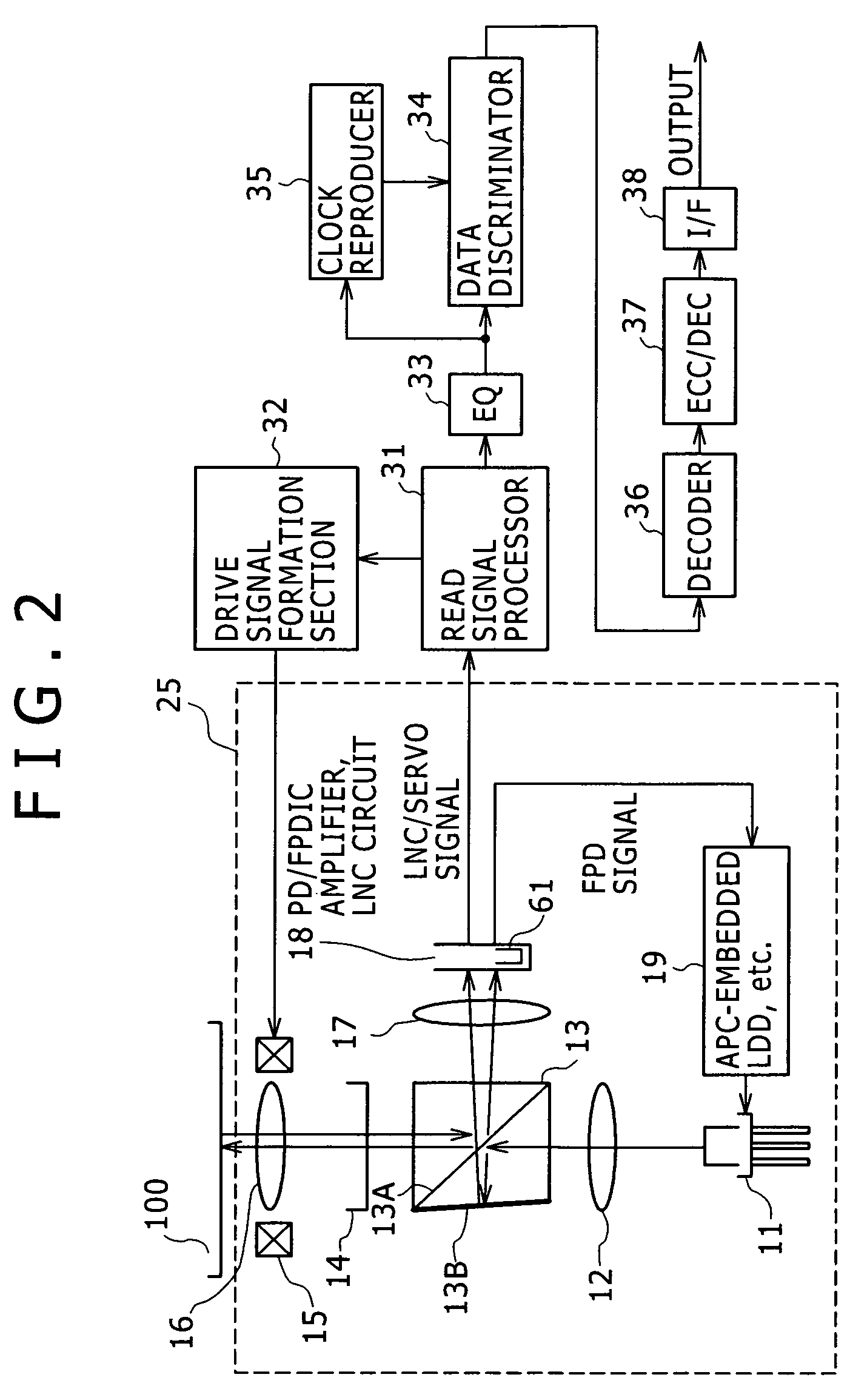
[0033]The light pickup section 1 includes a laser diode 11, a collimator lens 12, a polarizing splitter 13, a quarter wave plate 14, a coil system 15 for controlling focus, an objective lens 16, a condenser lens 17, an integrated element (hereinafter referred to as a PDIC) 21 embedding a main photodiode (hereinafter referred to as a main PD) and an amplifier, an integrated element (hereinafter referred to as a FPDIC) 22 embedding an front photodiode (hereinafter referred to as a front PD) and an amplifier, a laser noise cancel circuit 61, and a laser diode ...
second embodiment
[Second Embodiment]
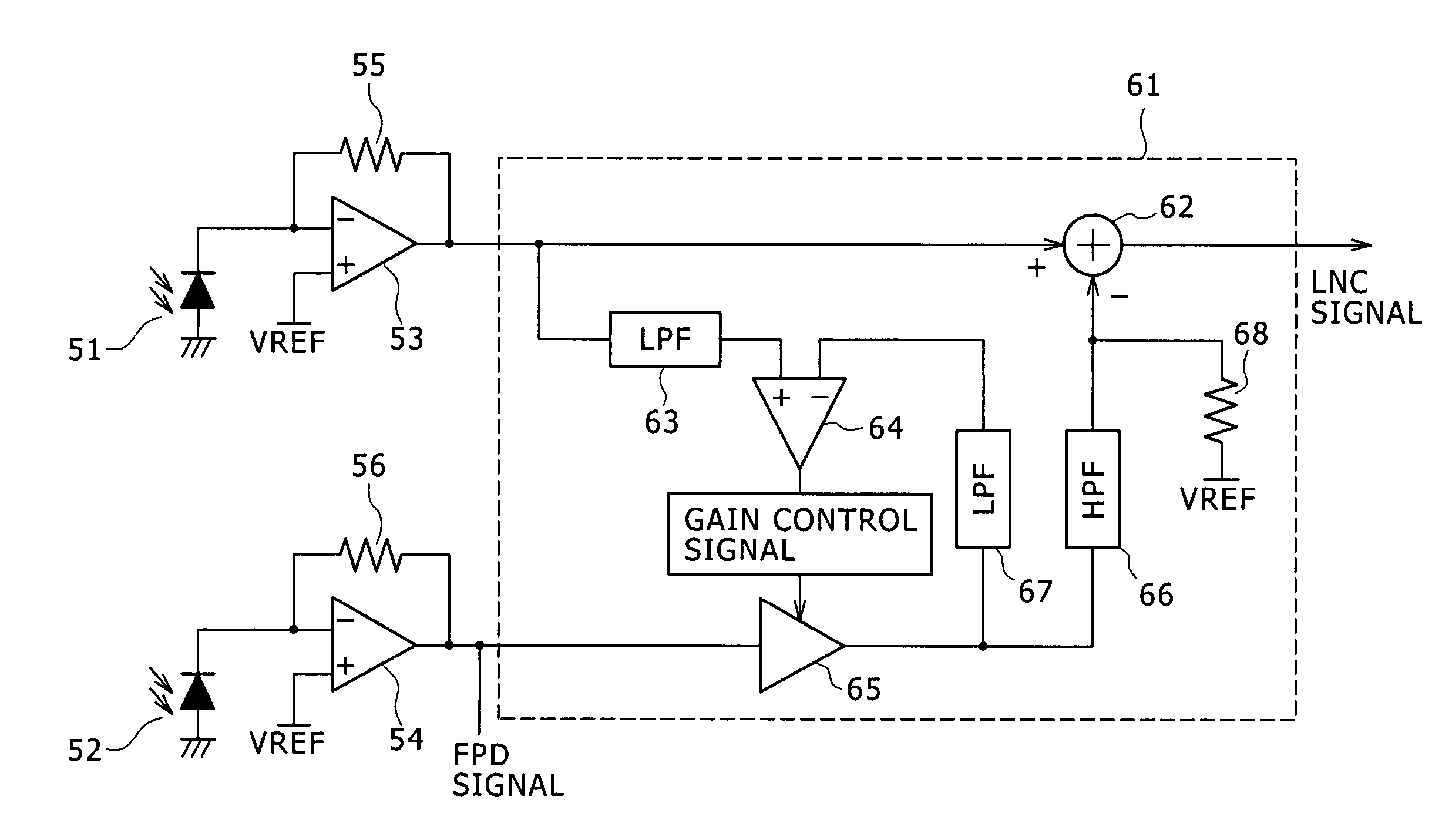
[0061]FIG. 4 is a circuit diagram showing a specific example of the laser noise cancel circuit 61 shown in FIG. 3. In FIG. 4, the same signs are assigned to the same circuit elements as those shown in FIG. 3 and descriptions are omitted herefrom.
[0062]In a laser noise cancel circuit 71 shown in FIG. 4, the amplifier 65 shown in FIG. 3 is replaced with a non-inverting amplifying circuit including a differential amplifier 520, resistors 521 and 522, and a MOS resistor (MOS resistor element) 523, so that application of the MOS resistor 523 as a return resistor leads a resistance value into variable, and by using the MOS resistor 523 as a return resistor, a resistance value of the MOS resistor 523 can be adjusted. Also by using a MOS resistor as a return resistor, the output from a differential amplifier 64 and a gain from the noninverting amplifying circuit is automatically adjusted, so as to determine a DC level of the output from the differential amplifier 520 to b...
third embodiment
[Third Embodiment]
[0065]FIG. 5 is a circuit diagram showing another specific example of the laser noise cancel circuit 61 shown in FIG. 3.
[0066]In FIG. 5, the same signs are assigned to the same circuit elements as those shown in FIG. 3 and FIG. 4, and descriptions thereof are omitted herefrom.
[0067]In a laser noise cancel circuit 81 shown in FIG. 5 in the third embodiment, the amplifier 65 shown in FIG. 3 is replaced with a non-inverting amplifying circuit including a differential amplifier 520, resistors 521 and 533, and a MOS resistor (MOS resistor element) 532. Using a fixed resistor 533 as a return resistor for the differential amplifier 520, while inserting the MOS resistor 532 as a resistor between a reverse phase input terminal of the differential amplifier 520 and a reference voltage VREF, by adjusting a resistant value of this resistor 532 with the output from a differential amplifier 64, a gain from the noninverting amplifying circuit is automatically adjusted, so as to d...
PUM
| Property | Measurement | Unit |
|---|---|---|
| frequency | aaaaa | aaaaa |
| resistance | aaaaa | aaaaa |
| temperature | aaaaa | aaaaa |
Abstract
Description
Claims
Application Information
 - R&D
- Intellectual Property
- Life Sciences
- Materials
- Tech Scout
- Unparalleled Data Quality
- Higher Quality Content
- 60% Fewer Hallucinations
Browse by: Latest US Patents, China's latest patents, Technical Efficacy Thesaurus, Application Domain, Technology Topic, Popular Technical Reports.
© 2025 PatSnap. All rights reserved.Legal|Privacy policy|Modern Slavery Act Transparency Statement|Sitemap|About US| Contact US: help@patsnap.com


