Optical rotary data transmission device with active termination

a technology of optical rotary data transmission and active termination, which is applied in the direction of optics, optical light guides, instruments, etc., can solve the problems of large optical transmission loss, relatively high fabrication cost, and device series, and achieve low cost, reliable transmission, and low optical attenuation

Inactive Publication Date: 2006-12-12
SCHLEIFRING & APPBAU
View PDF11 Cites 3 Cited by
  • Summary
  • Abstract
  • Description
  • Claims
  • Application Information

AI Technical Summary

Benefits of technology

[0011]The invention is based on the object of designing a relatively low cost device for transmitting optical signals between two units that are rotatable with respect to each other, in such manner that a reliable transmission is made possible with low optical attenuation, for large diameter devices, high mechanical movement speeds, and high data rates. Furthermore, it is the object of a special embodiment of the invention to design the device so that also signals having period lengths which are short compared with the time of propagation of the light around the circumference of the device may be transmitted. It is another object of the invention to provide a method for operating a device for transmission of modulated optical signals between units.

Problems solved by technology

Here a basic problem consists of designing a means for carrying light along the circumference of the device, and also suitable means for coupling light in or out.
However, this device has a whole series of disadvantages.
Thus, an optical transmission loss is comparatively large owing to multiple reflections at relatively steep angles.
Furthermore, the fabrication costs are relatively high, because of the oppositely disposed mirror-finished surfaces.
Wideband data transmission with period lengths of the modulation signal which are substantially shorter than the transit time of the signal around the circumference of the device is not possible, because signals are received along multiple-paths at positions of the receiver close to the transmitter.
However, even this patent specification sets out no effective solution of the problem of bandwidth limitation.
Here too, the problem of bandwidth limitation has not been solved.
Here too the limitation applies that the period length of the modulation signal must be substantially shorter than the transit time of the light around the circumference of the device.
Therefore the system costs rise in proportion to the bandwidth.

Method used


Image

  • Optical rotary data transmission device with active termination
  • Optical rotary data transmission device with active termination
  • Optical rotary data transmission device with active termination

Examples


Embodiment Construction

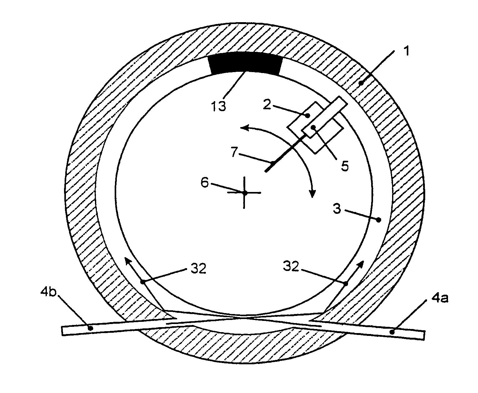
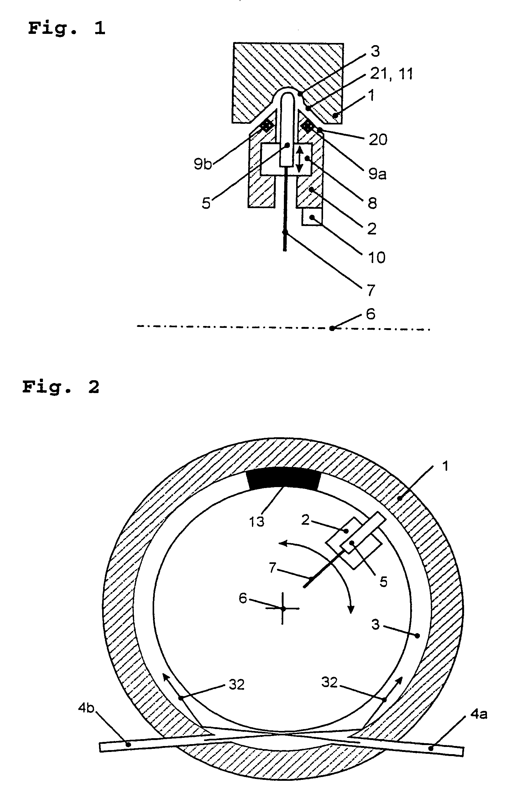
[0022]FIG. 1 shows in a schematic form a section of a device according to the invention. In this, a first unit 1 and also a second unit 2 are depicted as being discs having a central bore, which are supported for rotation about a rotation axis 6. Here a light guide 3 is shown by way of example as being a trench having a mirror finish on the inside. It extends around the entire circumference of the first unit. In engagement with this trench is a second light coupler 5 that is assigned to the second unit 2. This light coupler taps the light carried in the light guide, and relays it with a light-guiding fiber 7. A hydrodynamic bearing means, and also an electrodynamic bearing regulation, are provided for an exact alignment of the light guide and the second light coupler along one axis. The hydrodynamic bearing means is based on a thin air film formed between a first bearing face 21 and a second bearing face 20 by the movement of the two units with respect to each other. Additional mean...


PUM


Abstract

A device for transmitting modulated optical signals between units comprises a first unit and a second unit, the first unit being supported to be rotatable with respect to the second unit, a light guide along a circular track on the first unit, a first and a second light coupler for coupling light signals into or out of the light guide, the second light coupler being disposed on the second unit and movable with respect to the light guide. For an achievement of a high transmission bandwidth, a controllable absorber is provided in the light guide to prevent a propagation of light along a plurality of paths between the two units. In a method for operating the device, the absorber is controlled so that modulated light signals from the first and the second directions have a same amplitude at a point at which the modulated light signals have the same phase.

Description

BACKGROUND OF THE INVENTION[0001]1. Field of the Invention[0002]The invention relates to a device for transmitting optical signals between units rotatable relative to each other. Devices of this kind are preferably used in computer tomographs.[0003]2. Description of the Prior Art[0004]Various devices are known for transmitting optical signals between units that are rotatable relative to each other, particularly with an unobstructed inner diameter. Here a basic problem consists of designing a means for carrying light along the circumference of the device, and also suitable means for coupling light in or out. For application in computer tomographs, devices of this kind must have large unobstructed inner diameters of a magnitude of 1 meter. During rotation, the circumferential speed may be of a magnitude of 20 m / s. At the same time, data rates of more than 1 gigabyte per second (gigabaud) should be feasible.[0005]Thus, the U.S. Pat. No. 4,109,997 discloses an optical rotary data transm...

Claims


Application Information

Patent Timeline
Patent Type & Authority Patents(United States)
IPC IPC(8): G02B6/26
CPCG02B6/3604G02B6/266
Inventor SCHILLING, HARRYRANK, MATTHIASISERT, MAREN
Owner SCHLEIFRING & APPBAU
Why Eureka
Try Eureka