Utility trenching and sidewalk system

a technology for utilities and sidewalks, applied in the field of utility trenches, can solve the problems of buried utility cables, many drawbacks, and the danger of cables being severed or damaged during excavation by homeowners, developers, or other utility providers, and achieve the effect of less susceptible to rocking or shifting, and convenient transportation

Inactive Publication Date: 2006-12-19
EDE HLDG
View PDF31 Cites 47 Cited by
  • Summary
  • Abstract
  • Description
  • Claims
  • Application Information

AI Technical Summary

Benefits of technology

[0011]In another embodiment of the invention, a cavity is formed in the sidewalls and bottom wall of the module. The cavity may be filled with poured, wet concrete through apertures provided in the sidewalls. In this embodiment, the cavity serves as a concrete mold to create a durable utility trenching system after the concrete has cured. Advantageously, th

Problems solved by technology

Buried utility cables, however, suffer many drawbacks.
Such non-uniform burying of cables may lead to confusion regarding utility company rights of way and creates the danger of cables being severed or damaged during excavation by homeowners, developers, or other utility providers.
If the cables are severed or otherwise damaged, repair or replacement requires the costly and time-consuming process of digging up of the buried cables.
Furthermore, cables which are buried in the earth must be manufactured with relatively expensive insulation to protect the cables against moisture, heat, and damage from rodents.
Previous trenching systems have typically been made from precast sections of concrete and are thus very heavy

Method used


Image

  • Utility trenching and sidewalk system
  • Utility trenching and sidewalk system
  • Utility trenching and sidewalk system

Examples


Embodiment Construction

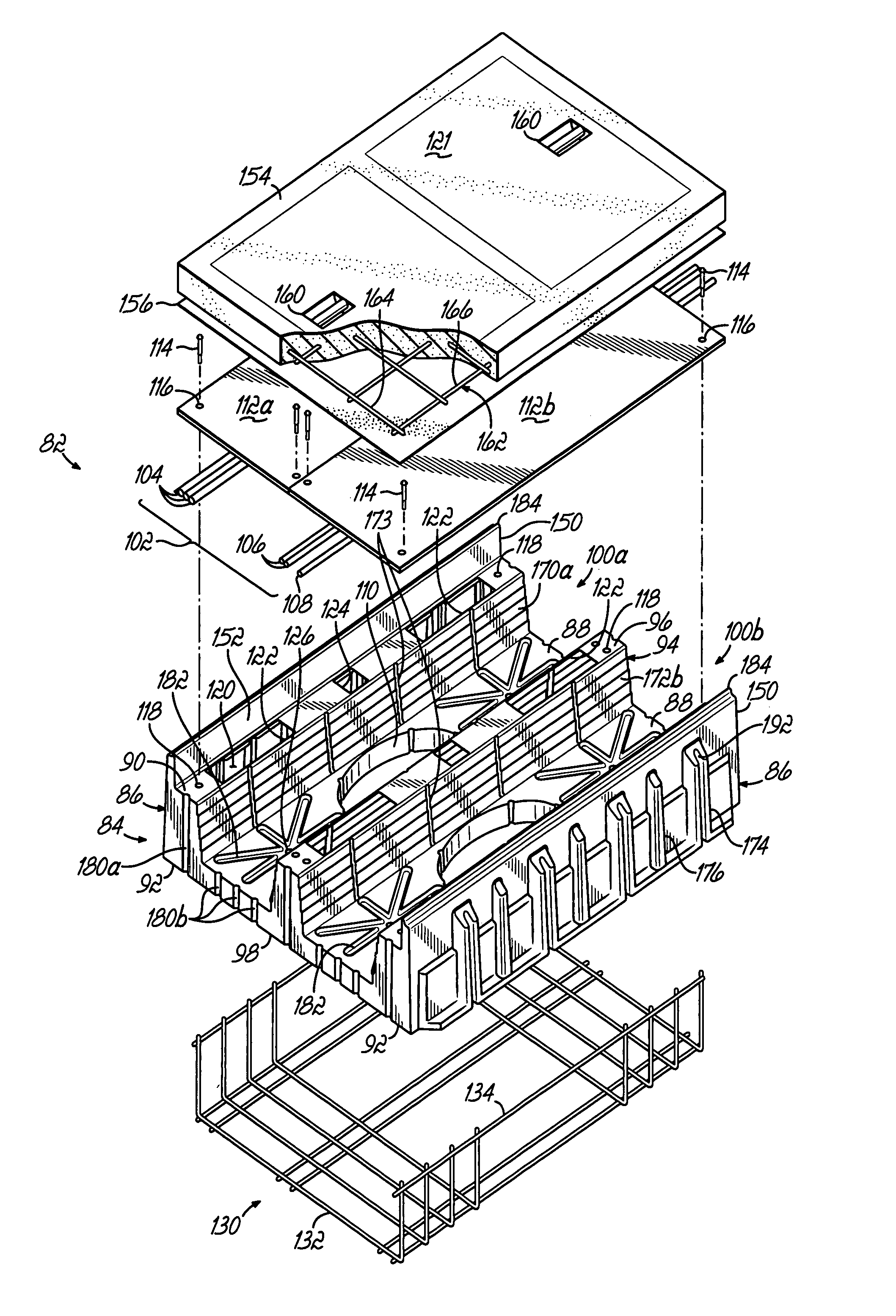
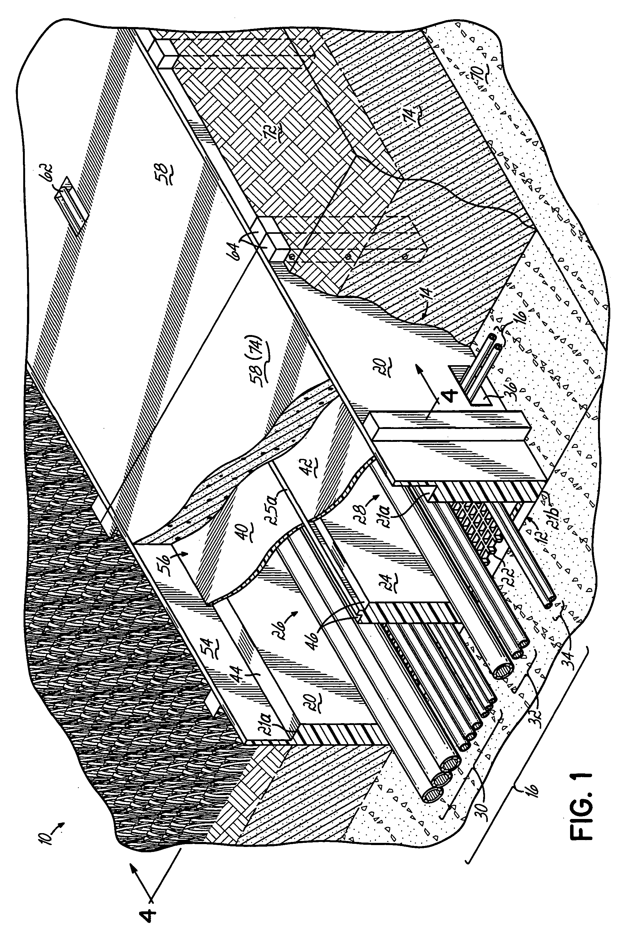
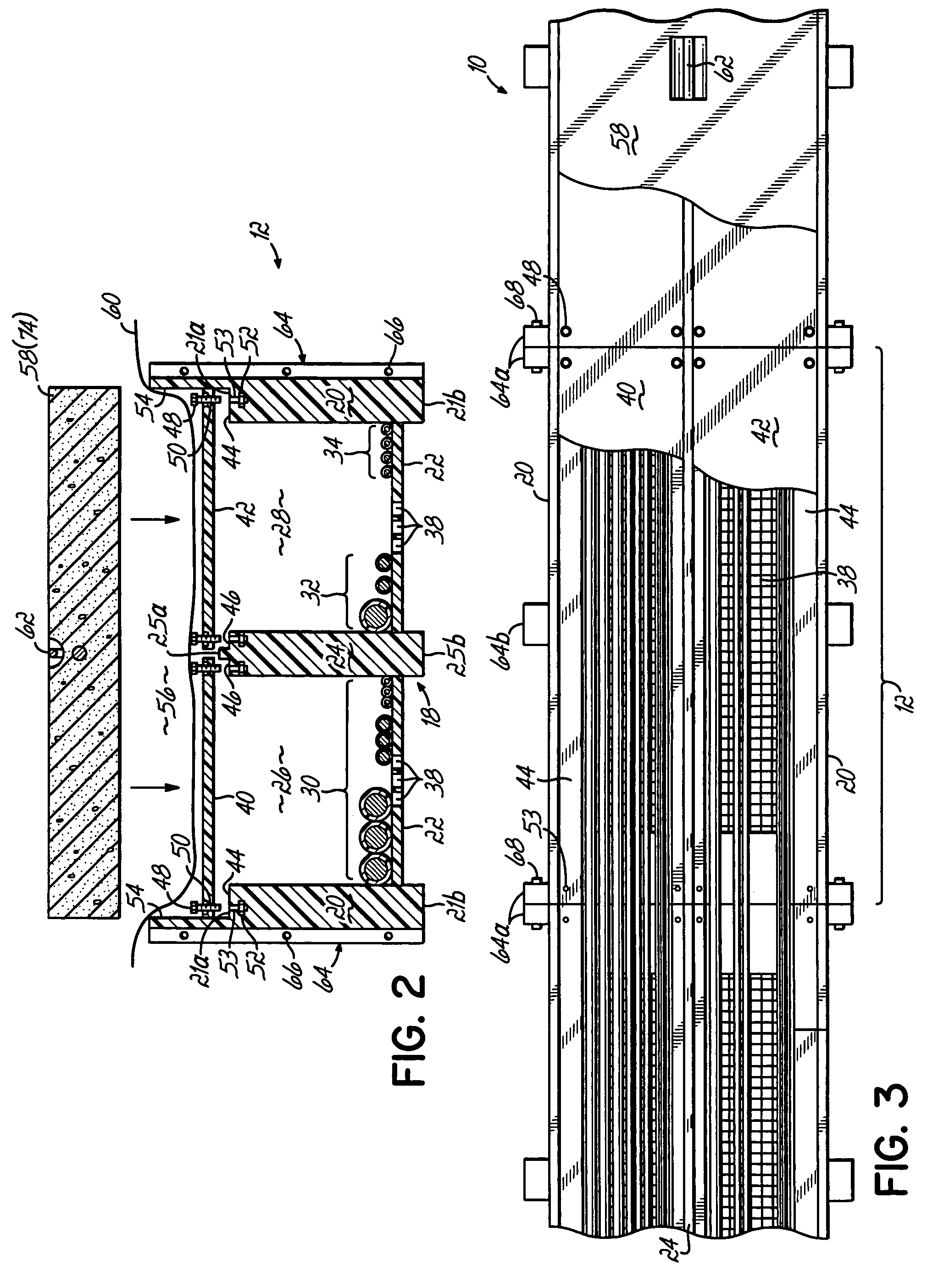
[0029]An exemplary utility trenching and sidewalk system 10 of the present invention is shown in FIGS. 1–5 in which like numerals are used to refer to like components. The trenching system 10 comprises a series of modular units 12 placed in an excavated trench 14 adjacent one another, longitudinally end to end, in an abutting relationship to form a continuous conduit for routing and protecting utility cables 16 laid within the conduit. Referring particularly to FIG. 2, the module 12 comprises a channel section 18 formed by opposing, and advantageously substantially parallel, outer sidewalls 20 and a bottom wall 22. Each outer sidewall has a top edge 21a and a bottom edge 21b, and the bottom wall 22 may be disposed proximate the bottom edges 21b. An inner sidewall 24 having a top edge 25a and a bottom edge 25b may be situated between the outer sidewalls 20, advantageously parallel thereto, with the bottom edge 25b proximate bottom wall 22. The inner sidewall 24 divides the channel 18...


PUM


Abstract

A utility trenching and sidewalk system comprising modular utility sidewalk units which may be assembled together to form a cable trench. The modular units are formed from plastic composite material and include sidewalls, a bottom wall and covers which define a chamber for housing utility cables. A cavity formed in the sidewalls and bottom wall is filled with concrete through apertures in the sidewalls. The covers are removable from the module to provide access to the chamber. The module further includes a recess for receiving a paving material which serves as a sidewalk surface in the installed system.

Description

[0001]This application is a continuation-in-part of application Ser. No. 10 / 038,721, filed Jan. 3, 2002 now U.S. Pat. No. 6,702,510 the disclosure of which is fully incorporated herein by reference.FIELD OF THE INVENTION[0002]The present invention pertains to utility trenches for routing utility cables.BACKGROUND OF THE INVENTION[0003]Utility cables are often buried beneath the earth to hide the cables and to protect them from damage, especially in residential or business areas. Buried utility cables, however, suffer many drawbacks. For example, various utility providers (such as electric, telephone and television providers) often work independently and bury their respective cables in separate locations. Such non-uniform burying of cables may lead to confusion regarding utility company rights of way and creates the danger of cables being severed or damaged during excavation by homeowners, developers, or other utility providers. If the cables are severed or otherwise damaged, repair ...

Claims


Application Information

Patent Timeline
IPC IPC(8): E04C2/52H02G9/04
CPCH02G9/04
Inventor BARKER, JAMES E.
Owner EDE HLDG
Why Eureka
Try Eureka