
Autostereoscopic projection viewer

a projection viewer and stereoscopic technology, applied in the field of stereoscopic image production methods and systems, can solve the problems of not producing system failure to produce images with the optical characteristics of real images, and need for viewing aids

Inactive Publication Date: 2006-12-19
LAWRENCE LIVERMORE NAT SECURITY LLC
View PDF15 Cites 37 Cited by
  • Summary
  • Abstract
  • Description
  • Claims
  • Application Information

AI Technical Summary

Problems solved by technology

Currently, images provided by conventional 3D viewing systems are too small or close to appear as full scale.
In addition, such systems do not produce images with the optical characteristics of a real image and often require the need for viewing aids.
From a viewer's perspective, the wearing of special glasses is cumbersome and from a provider's perspective, expensive for such viewing aids.

Method used


Image

  • Autostereoscopic projection viewer
  • Autostereoscopic projection viewer
  • Autostereoscopic projection viewer

Examples


Embodiment Construction

[0021]Referring now to the drawings, specific embodiments of the invention are shown. The detailed description of the specific embodiments, together with the general description of the invention, serve to explain the principles of the invention.

[0022]Unless otherwise indicated, all numbers expressing quantities of ingredients, constituents, reaction conditions and so forth used in the specification and claims are to be understood as being modified in all instances by the term “about”. Accordingly, unless indicated to the contrary, the numerical parameters set forth in the specification and attached claims are approximations that may vary depending upon the desired properties sought to be obtained by the subject matter presented herein. At the very least, and not as an attempt to limit the application of the doctrine of equivalents to the scope of the claims, each numerical parameter should at least be construed in light of the number of reported significant digits and by applying or...


PUM


Abstract

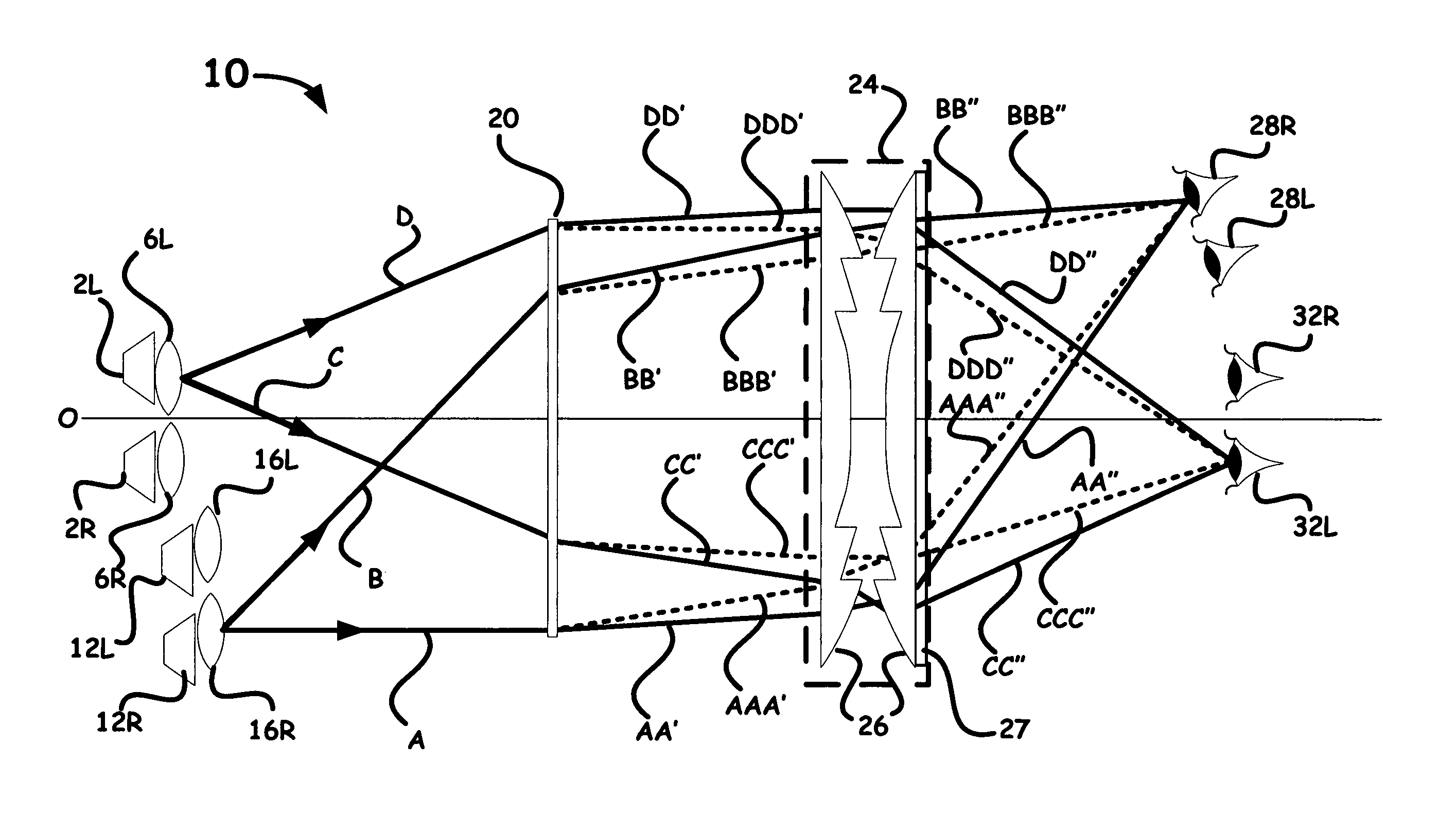
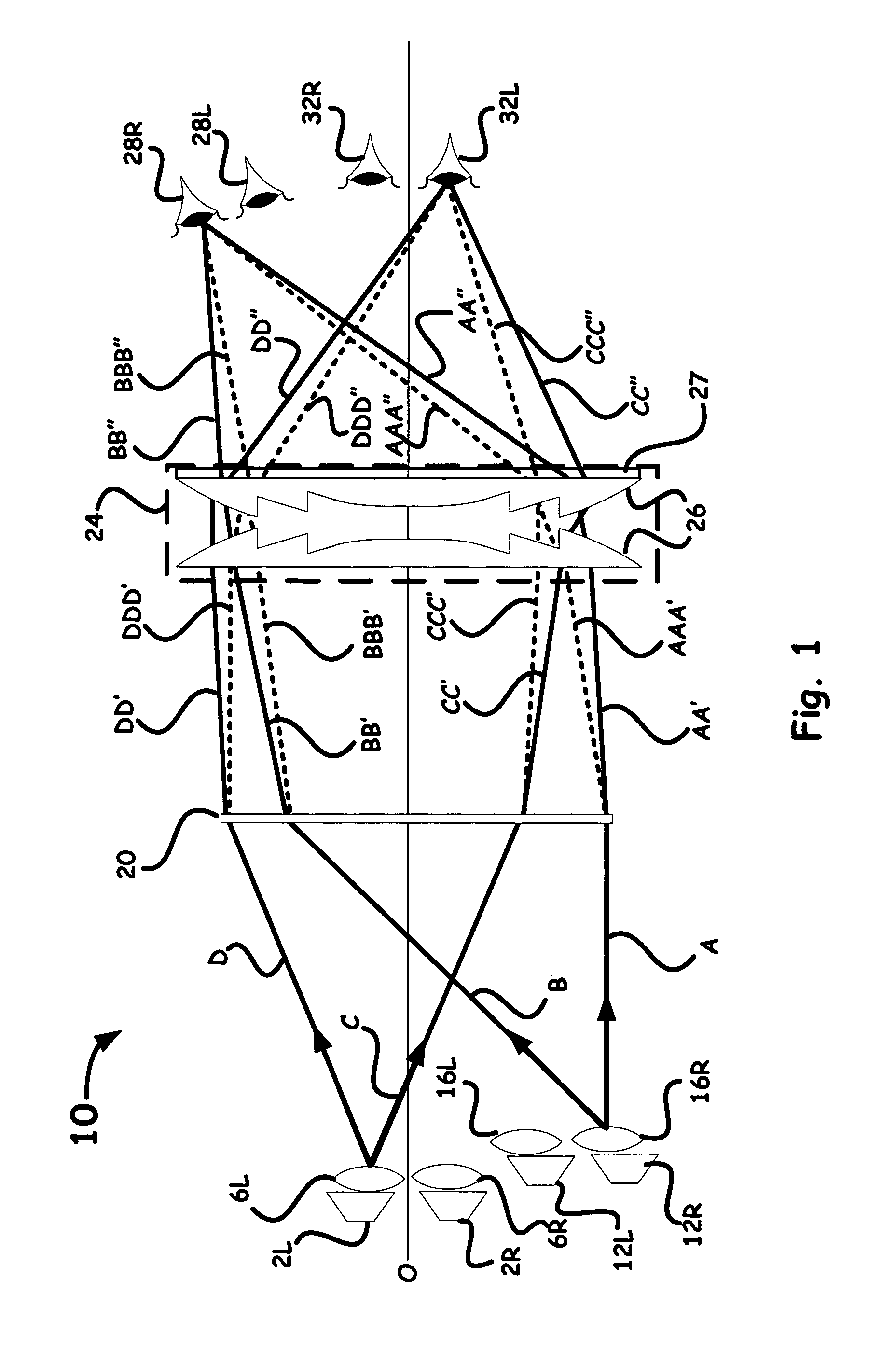
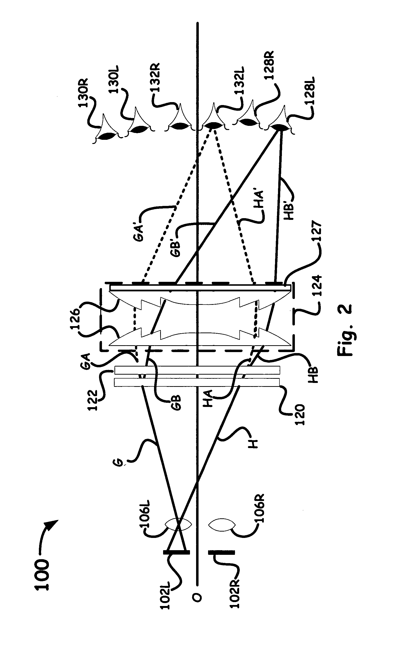
An autostereoscopic viewer is employed to produce aberration corrected images to simulate a virtual presence by employing pairs of projector optical components coupled with an image corrector plate and a field lens. Images are designed with magnifications and optical qualities and positioned at predetermined eyezones having controlled directional properties. The viewer's eyes are positioned in these eyezones. The size of these zones is related to the aperture of the projection lenses, the magnification produced by the Fresnel(s), and the optical properties and position of the image corrector plate.

Description

[0001]The United States Government has rights in this invention pursuant to Contract No. W-7405-ENG-48 between the United States Department of Energy and the University of California for the operation of Lawrence Livermore National Laboratory.BACKGROUND OF THE INVENTION[0002]1. Field of the Invention[0003]The present invention relates to a method and system for producing stereoscopic images (i.e., one view for each eye of an observer), and more particularly to an autostereoscopic system and method that produces aberration corrected images with an apparent size, distance, color and detail to simulate a virtual presence.[0004]2. Description of Related Art[0005]Recently, 3D systems have become of interest because technology has made 3D-like displays a part of daily life. For example, present technology can provide holographic images on credit cards and on driving licenses. We have home desktop computers that can generate interactive displays with stereoscopic image pairs. Three dimensi...

Claims


Application Information

Patent Timeline
Patent Type & Authority Patents(United States)
IPC IPC(8): G03B21/00G03B21/60G02B27/00G03B35/00H04N13/04G02B27/22H04N13/363
CPCG02B27/225H04N13/0404H04N13/0459H04N13/305H04N13/363G02B27/0062
Inventor TOEPPEN, JOHN S.
Owner LAWRENCE LIVERMORE NAT SECURITY LLC
Learn More