

Cup attaching apparatus
a technology for attaching apparatuses and cups, which is applied in the direction of grinding drives, manufacturing tools, instruments, etc., can solve the problems of coating cracking and lens deformation
- Summary
- Abstract
- Description
- Claims
- Application Information
AI Technical Summary
Benefits of technology
Problems solved by technology
Method used
Image

Examples
first embodiment
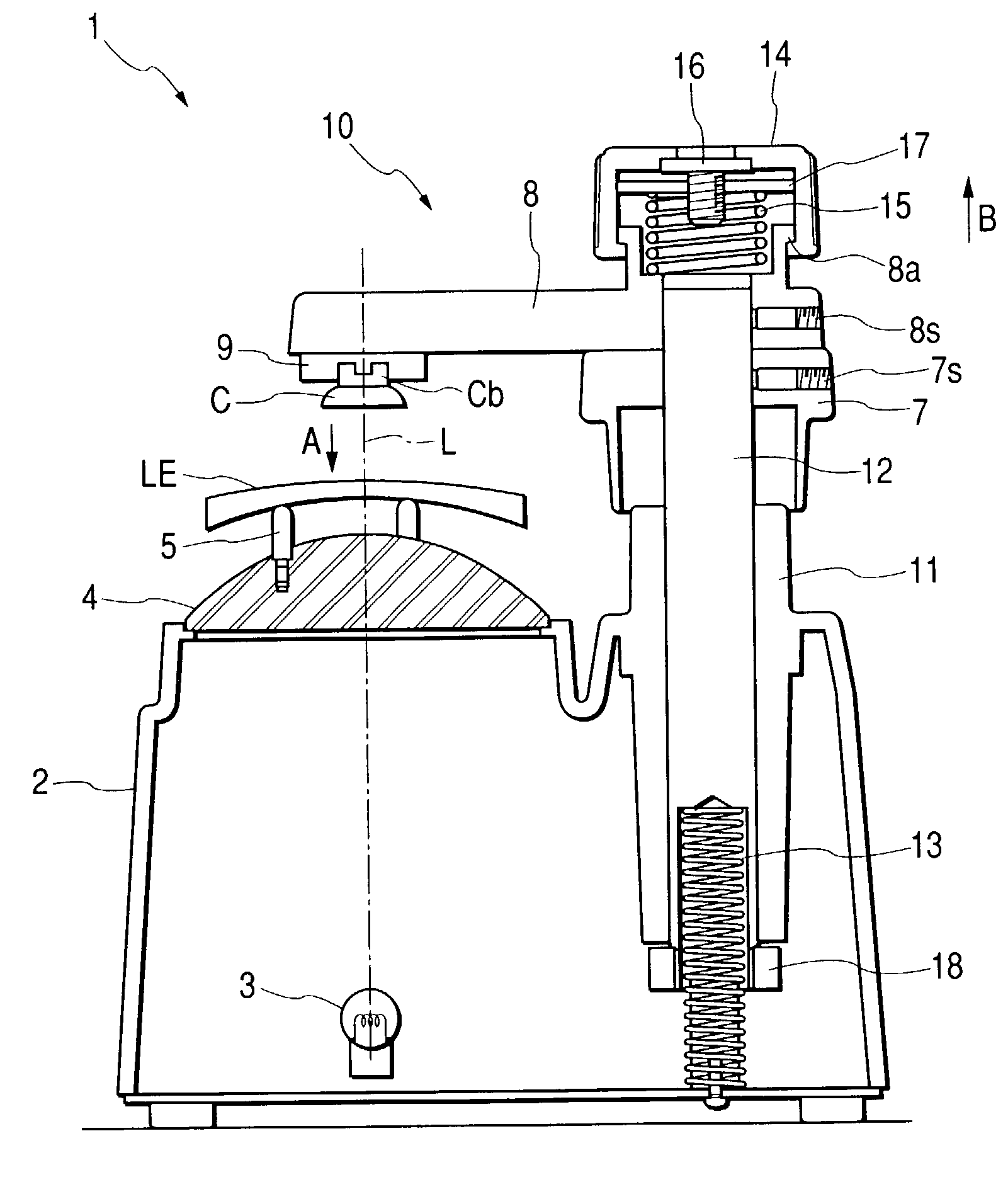
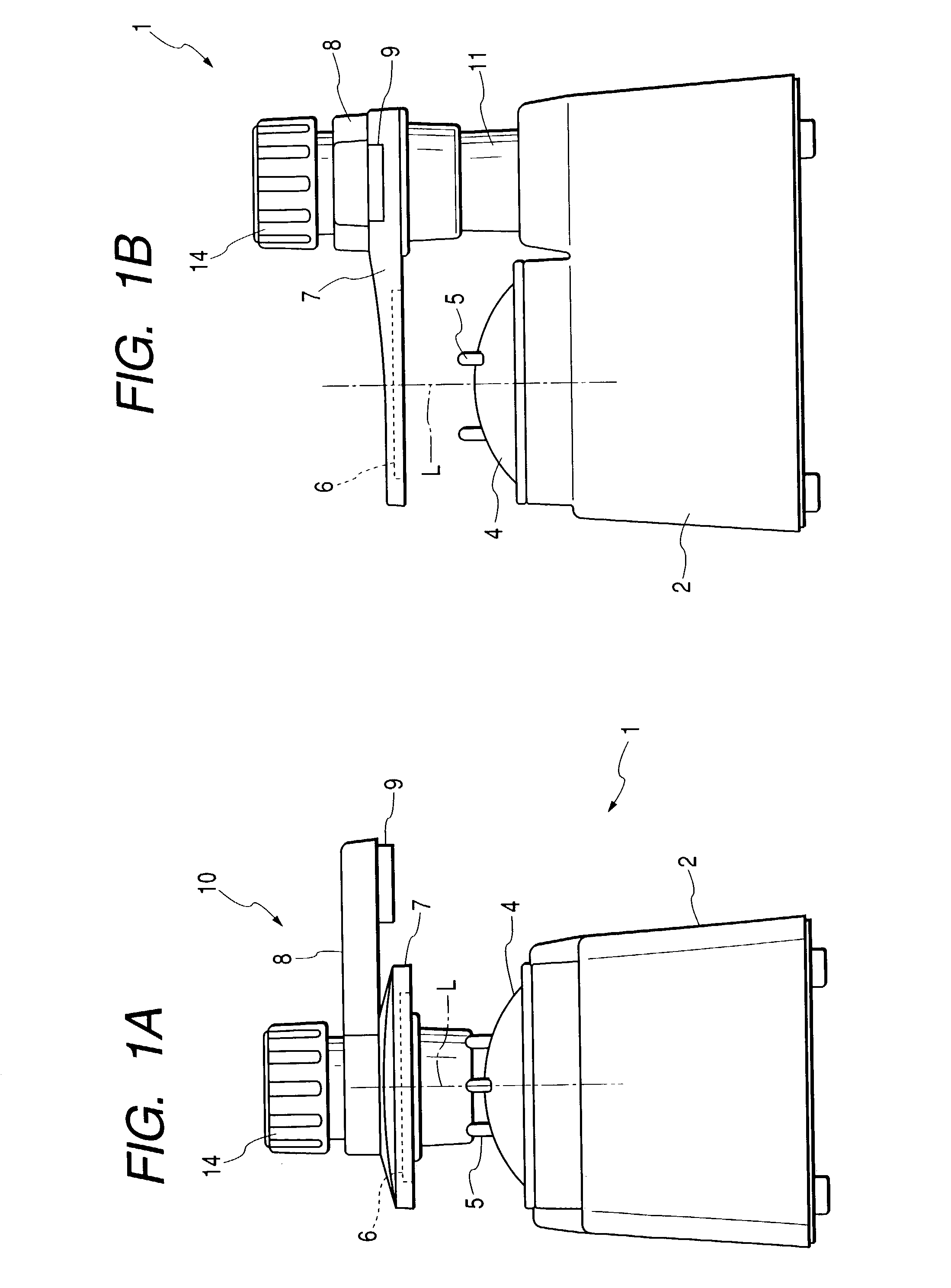
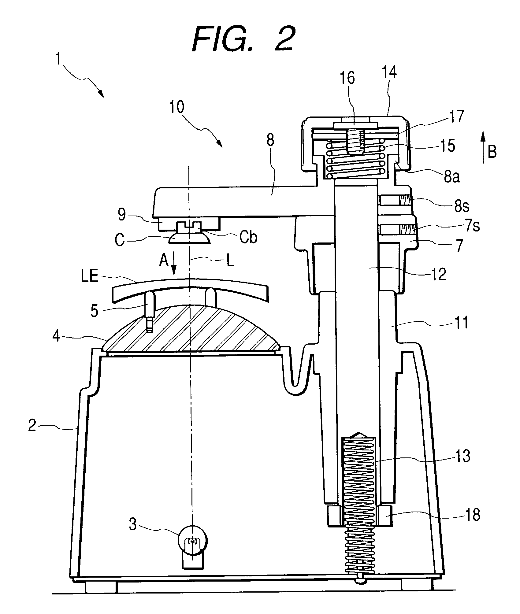
[0053]Referring now to the drawings, a description will be given of the embodiments of the invention. FIGS. 1A and 1B are external views of a cup attaching apparatus 1 in accordance with the invention, in which FIG. 1A is a front elevational view, and FIG. 1B is a side elevational view. FIG. 2 is a side elevational view of the interior of the apparatus 1, and FIG. 3 is a top view of the apparatus 1. It should be noted that FIGS. 1A, 1B, and 3 are diagrams in a case where a screen plate 6 is positioned on a reference axis L, and FIG. 2 is a diagram in a case where a cup fitting portion 9 is positioned on the reference axis L.
[0054]In FIGS. 1A, 1B, and 2, reference character L denotes a reference axis for cup attachment (alignment) . An illuminating light source 3 located on the reference axis L is provided inside a main body housing 2, and a condenser lens 4 is disposed on top of the main body housing 2. The lens 4 collimates the illumination light from the light source 3 into a para...
second embodiment
[0067]FIG. 4 is a diagram explaining a cup attaching apparatus 1′ in accordance with the invention, and elements identical to those of the preceding embodiment are denoted by the same reference numerals. A fitting portion 9′ for detachably holding the cup C is held on the underside of a distal end of an arm 8′ in such a manner as to be movable vertically in the direction of the reference axis L and to be non-rotatable. A spring 15′ for urging the fitting portion 9′ downward (in the direction of arrow A) relative to the arm 8′ is provided in a recessed portion 8b formed in the distal end of the arm 8′. In the same way as the spring 15 in the preceding embodiment, this spring 15′ has such a spring force that its urging force is greater than the upwardly urging force (in the direction of arrow B) of the spring 13 and that the spring 15′ is deformed when pressure greater than a predetermined pressure is applied thereto. Further, a spring presser plate 17′ for adjusting the initial defor...
third embodiment
[0070]FIG. 5 is a diagram explaining the invention. Although in each of the above-described embodiments an arrangement is provided to attach the cup by a manual operation, this embodiment shows an example in which the cup is attached by the driving force of a motor.
[0071]In the same way as the first embodiment, the cup C is fitted to the fitting portion 9 supported by an arm 40. Reference numeral 41 denotes a moving mechanism section and is constituted by a motor 42, a ball screw 43 attached to a rotating shaft of the motor 42, and the like. As the ball screw 43 is rotated, the arm 40 is moved vertically in the direction of the reference axis L. The driving of the motor 42 is controlled by a control unit 45. Connected to the control unit 45 are an input unit 46 for inputting various conditions, a start switch 47 for starting the cup attachment, and a memory 48. In the input unit 46, the type (suction type, seal type, etc.) of the cup C is inputted. The reason for this is that the at...
PUM
| Property | Measurement | Unit |
|---|---|---|
| deforming force | aaaaa | aaaaa |
| pressing force | aaaaa | aaaaa |
| pressure | aaaaa | aaaaa |
Abstract
Description
Claims
Application Information