Cooling device for battery pack and rechargeable battery

a rechargeable battery and cooling device technology, applied in the direction of secondary cell servicing/maintenance, cell components, cell component details, etc., can solve the problem of insufficient cooling at the other end, and achieve the effect of efficiently and uniformly cooling an individual rechargeable battery pack and reducing the height of the battery pack

Inactive Publication Date: 2006-12-19
PANASONIC CORP +1
View PDF12 Cites 43 Cited by
  • Summary
  • Abstract
  • Description
  • Claims
  • Application Information

AI Technical Summary

Benefits of technology

[0011]In light of the above-mentioned conventional problem, the present invention has an object of providing a cooling device for a battery pack and a rechargeable battery, which reduces a height of the battery pack including the cooling device and efficiently and uniformly cools an individual rechargeable battery.

Problems solved by technology

Even if a temperature at one end of the rechargeable battery is reduced, a temperature at the other end may not be sufficiently lowered.

Method used


Image

  • Cooling device for battery pack and rechargeable battery
  • Cooling device for battery pack and rechargeable battery
  • Cooling device for battery pack and rechargeable battery

Examples


first embodiment

[0028]A first embodiment of a cooling device for a battery pack and a rechargeable battery constituting the battery pack according to the present invention will be described with reference to FIGS. 1 to 4.

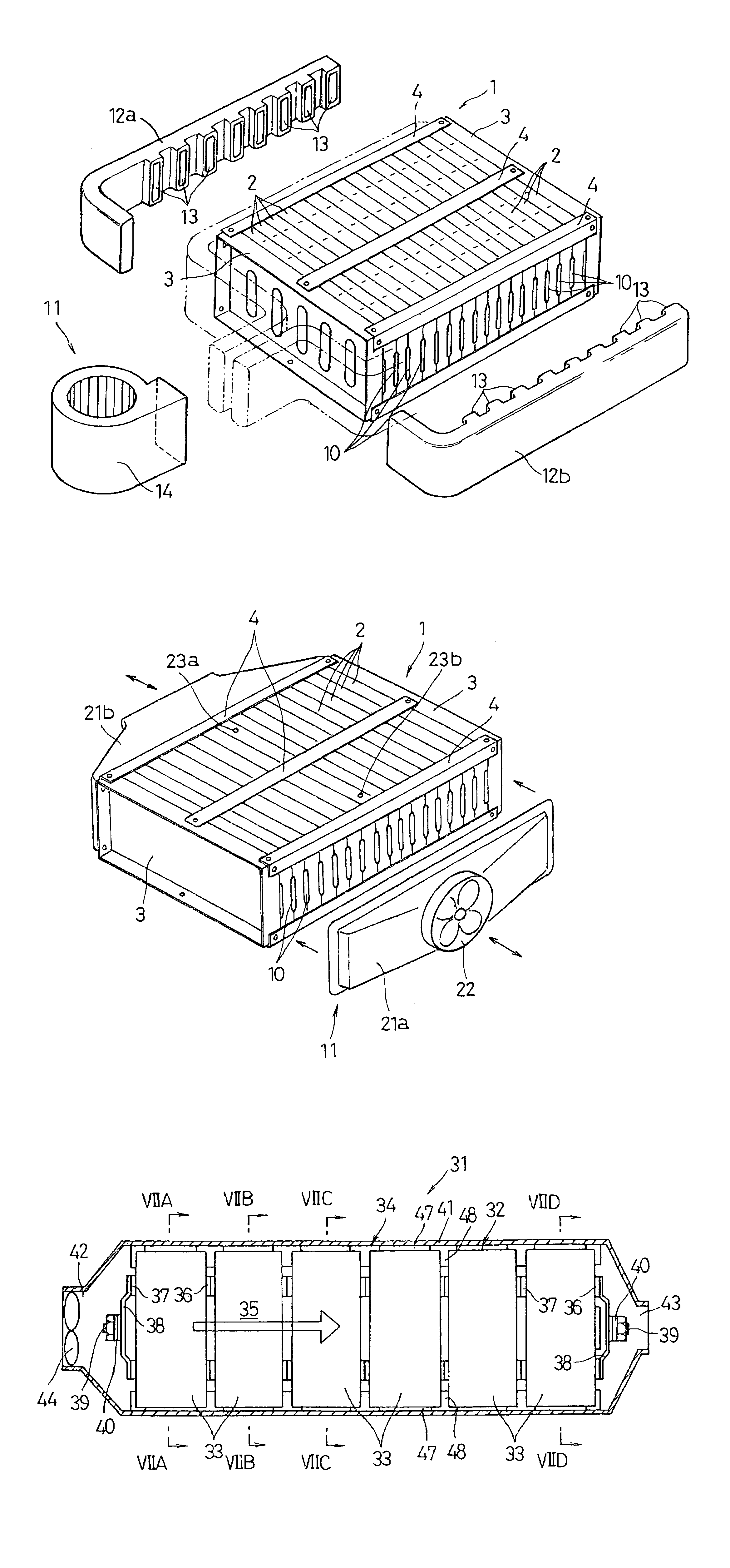
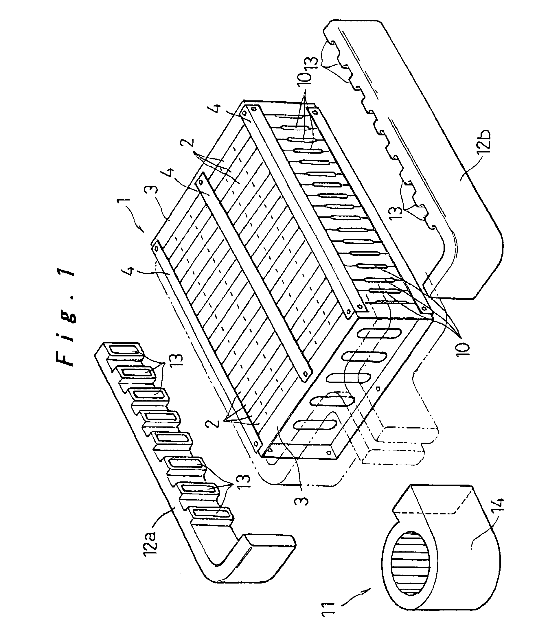
[0029]In FIG. 1, reference numeral 1 denotes a battery pack serving as a driving power source for electric vehicles including hybrid cars. The battery pack 1 includes ten to thirty rechargeable batteries 2 that are arranged in parallel. The rechargeable batteries 2 are interposed between a pair of end plates 3 provided on both ends of the rechargeable batteries 2 in a parallel direction so as to be integrally fixed with a binding member 4, thereby constituting the battery pack 1.

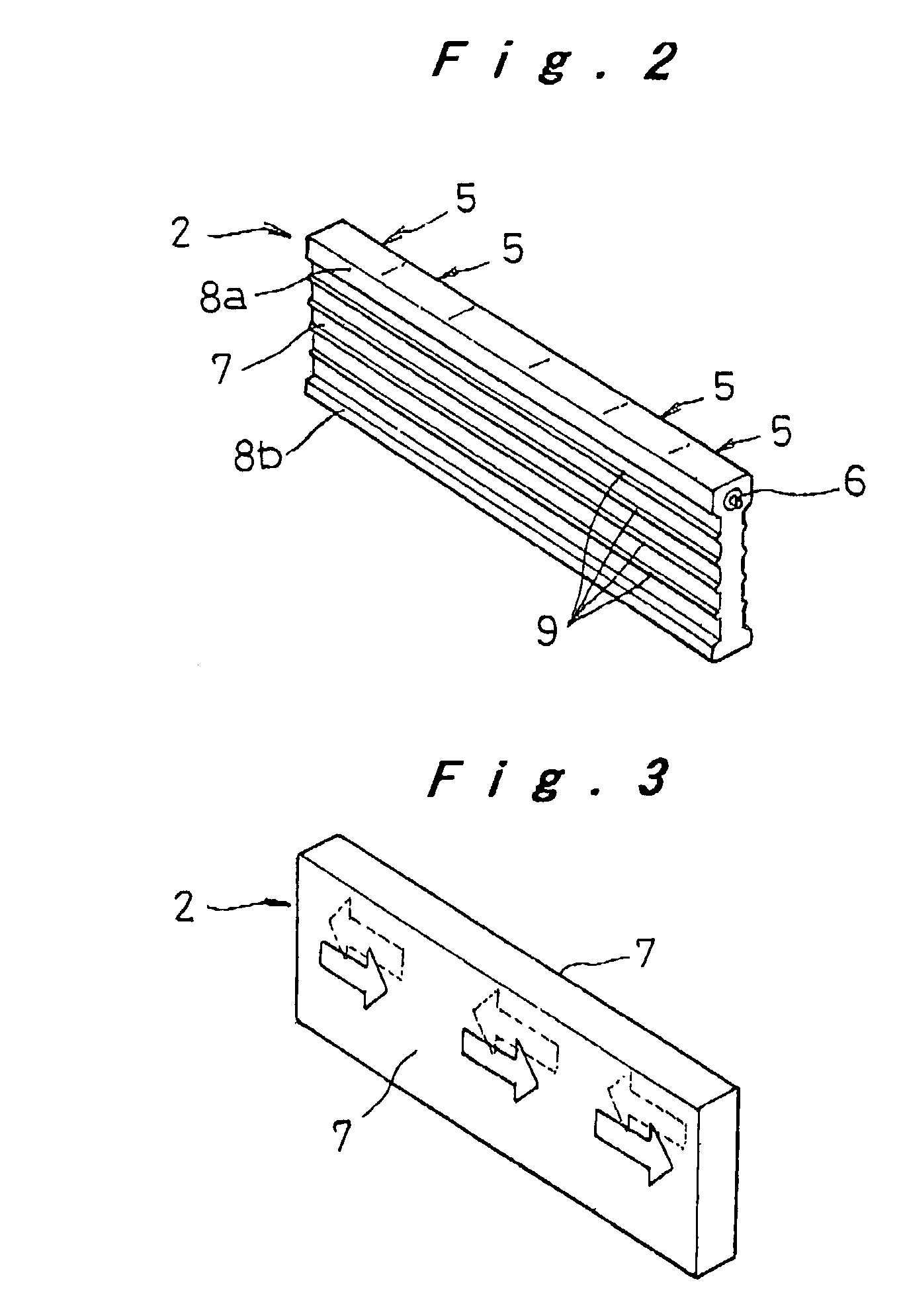
[0030]Each of the rechargeable batteries 2 has a flat prismatic form with a height larger than a thickness. A longer side face of the rechargeable battery 2 has a horizontal width larger than the height. The rechargeable battery 2 is constituted as a battery module including a plurality of (in the illustrat...

second embodiment

[0040]Next, a second embodiment of the cooling device for the battery pack according to the present invention will be described with reference to FIG. 5.

[0041]In the first embodiment, the cooling medium is delivered alternately in horizontally opposed directions to each of the cooling medium paths 10 between the rechargeable batteries 2. In this embodiment, the cooling medium is delivered from either of the horizontal directions (that is, from right or left) of the battery pack 1. When a difference in temperature is found to be a predetermined value or larger through detection of both right and left ends of the rechargeable battery 2, a delivery direction of the cooling medium is switched, thereby uniformly cooling each of the rechargeable batteries 2.

[0042]The cooling medium delivery device 11 of this embodiment includes a pair of cooling medium delivery hoods 21a and 21b on both sides of the battery pack 1 so as to deliver the cooling medium from either right or left direction to ...

third embodiment

[0045]Next, a third embodiment of the cooling device for the battery pack according to the present invention will be described with reference to FIGS. 6 to 8.

[0046]A battery pack 31 in the third embodiment includes a plurality of rechargeable batteries 32 that are arranged in parallel through spacers 34 made of a synthetic resin. Each of the rechargeable batteries 32 includes a plurality of prismatic cells 33, each having a prismatic metal case, which are arranged in a row so as to be connected in series. The spacers 34 form cooling medium paths 35, respectively.

[0047]A pair of connection terminals 36 having one polarity are provided on one shorter side face of each of the cells 33, which shorter side face is opposed to the arrangement direction of the cells 33. The connection terminals 36 are provided so as to penetrate through the case in an insulated state. On the other shorter side face of the cell 33, a pair of connection terminals 37 having the other polarity are provided by f...


PUM

PropertyMeasurementUnit
temperatureaaaaaaaaaa
temperaturesaaaaaaaaaa
areaaaaaaaaaaa

Abstract

In a battery pack including rechargeable batteries arranged in parallel, a cooling medium path for allowing a cooling medium to horizontally flow be formed between the rechargeable batteries. A cooling medium delivery device for delivering the cooling medium to the cooling medium path is provided so as to reduce a height of the battery pack including a cooling device. The cooling medium delivery device is constituted by a pair of cooling medium introduction ducts provided on both right and left sides of the battery pack, each having delivery ports for delivering the cooling medium alternately in horizontally opposed directions to each of the cooling medium paths, and a cooling medium compression transport device for supplying the cooling medium to both of the cooling medium introduction ducts.

Description

[0001]The present disclosure relates to subject matter contained in priority Japanese Patent Application Nos. 2002-136611 and 2003-49553, filed on May 13, 2002 and Feb. 26, 2003, respectively, the contents of which is herein expressly incorporated by reference in its entirety.BACKGROUND OF THE INVENTION[0002]1. Field of the Invention[0003]The present invention relates to a cooling device for a battery pack including a plurality of prismatic rechargeable batteries arranged in parallel and to such a rechargeable battery.[0004]2. Description of Related Art[0005]In a conventional battery pack, in order to prevent decrease in a battery output, charging / discharging efficiency, and battery service life due to the elevation of the battery temperature by heat generation that occurs along with charging / discharging, for example, Japanese Patent Laid-Open Publication No. 2001-167803 discloses a fan provided to upwardly send cooling air between cells included in the battery pack or between batte...

Claims


Application Information

Patent Timeline
Patent Type & Authority Patents(United States)
IPC IPC(8): H01M2/12H01M10/50H01M6/42H01M10/60H01M10/42H01M50/209H01M50/291
CPCH01M2/1077H01M10/4207H01M10/5004H01M10/5008H01M10/5016H01M10/502H01M10/5032H01M10/5038H01M10/5059H01M10/5067H01M10/5073H01M10/625H01M10/63H01M10/6563H01M10/647H01M10/652H01M10/6557H01M10/617H01M10/6566H01M10/613Y02E60/10H01M50/209H01M50/291
Inventor HAMADA, SHINJIETO, TOYOHIKO
Owner PANASONIC CORP
Why Eureka
Try Eureka