Inline air handler system and associated method of use

a handler system and air handler technology, applied in the direction of optical radiation measurement, separation process, instruments, etc., can solve the problems of affecting affecting the effect of everyone working or living in the premises, and a high cost of monitoring a number of factors

Active Publication Date: 2006-12-19
INVENSYS SYST INC +1
View PDF20 Cites 41 Cited by
  • Summary
  • Abstract
  • Description
  • Claims
  • Application Information

AI Technical Summary

Problems solved by technology

Therefore, to monitor a number of factors is a very costly proposition.
Another problem is that biohazards are present in the air as well as in the drinking water.
A significant issue is that viral or bacterial toxins can be recirculated within a building with an HVAC system so that eventually everyone working or living within the premises is eventually affected.
Yet another problem is that the filtration currently utilized with existing HVAC systems do not provide any indication as to when they are blocked or no longer working effectively.

Method used


Image

  • Inline air handler system and associated method of use
  • Inline air handler system and associated method of use
  • Inline air handler system and associated method of use

Examples


Embodiment Construction

[0031]In the following detailed description, numerous specific details are set forth in order to provide a thorough understanding of the invention. However, it will be understood by those skilled in the art that the present invention may be practiced without these specific details. In other instances, well-known methods, procedures and components have not been described in detail so as to obscure the present invention.

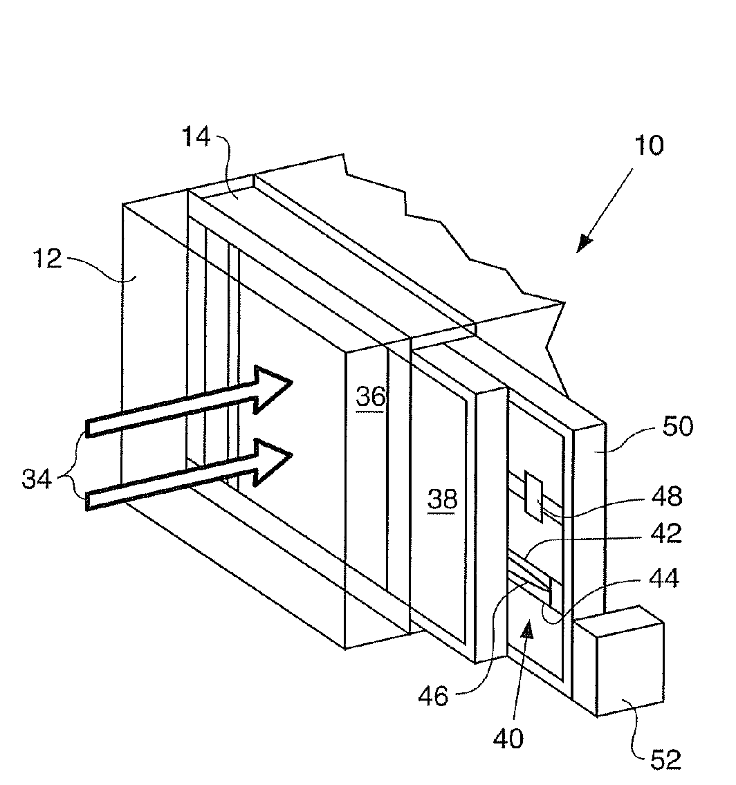
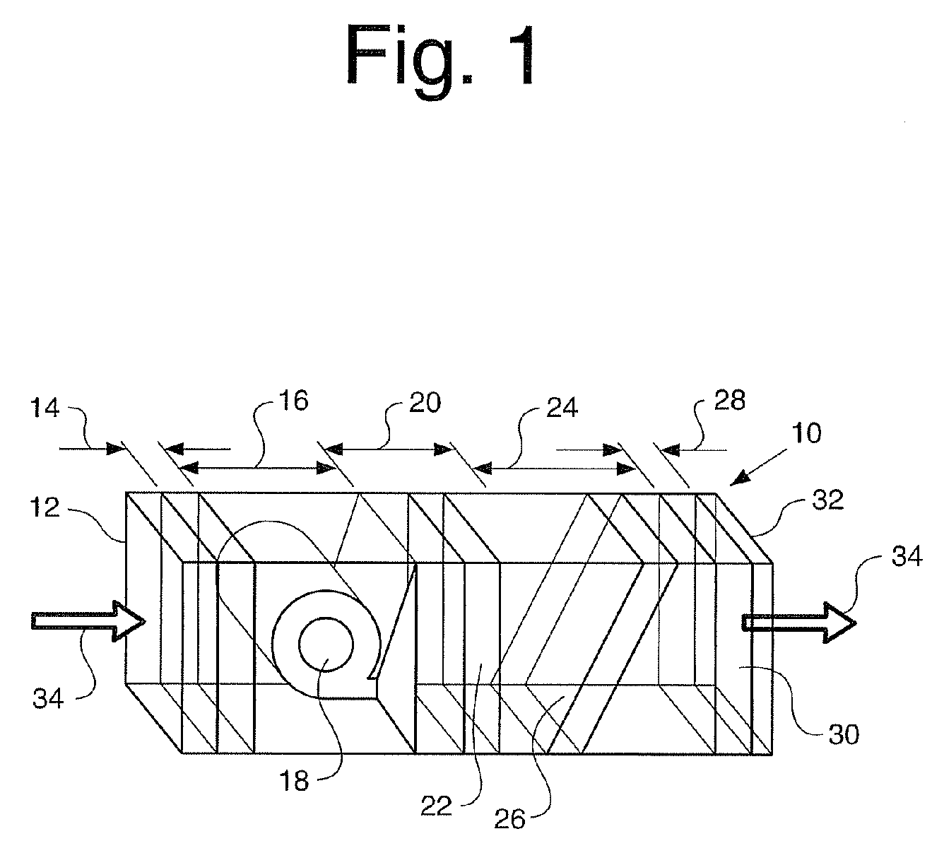
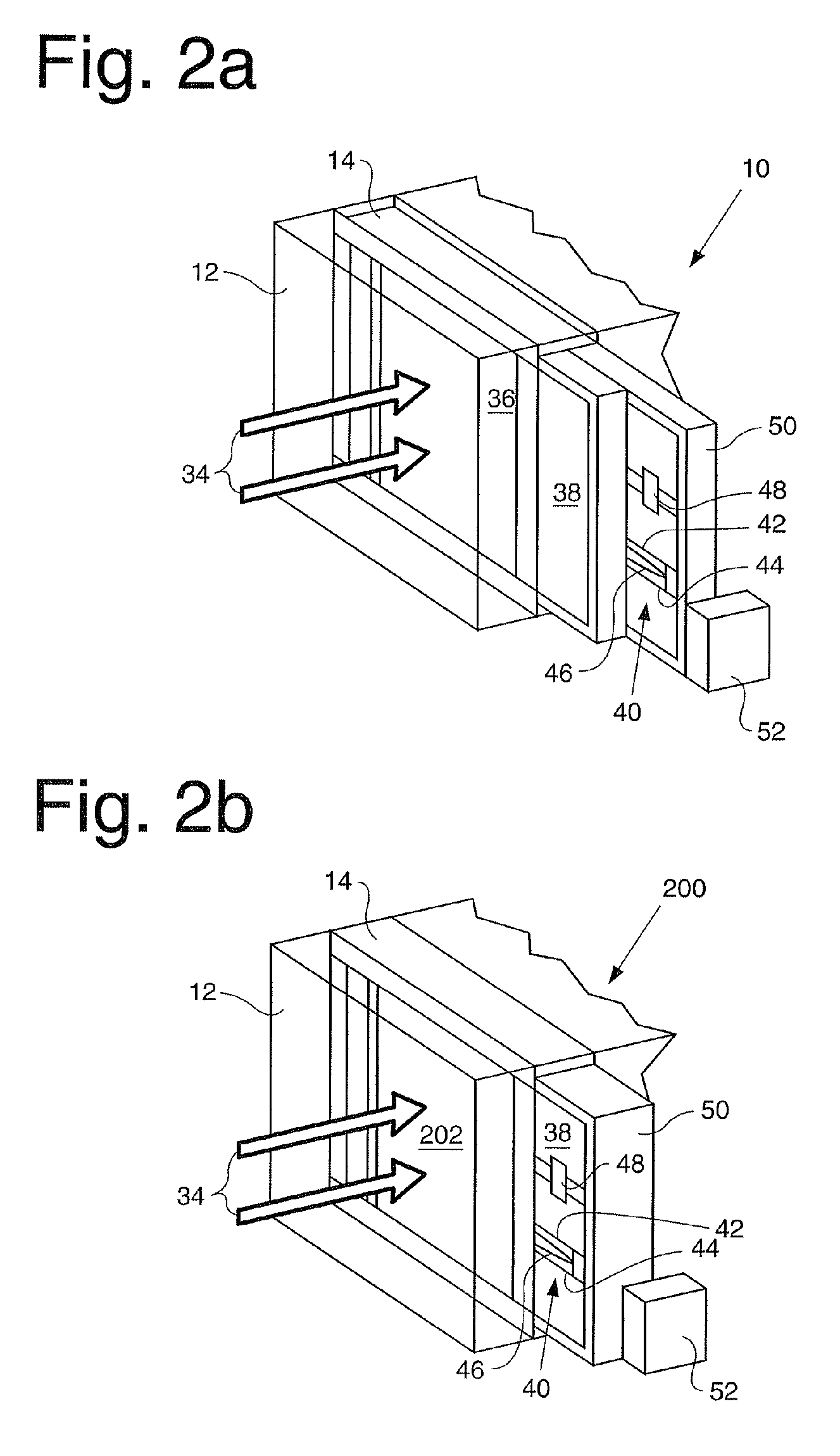
[0032]Referring now to the drawings, and initially to FIG. 1, a preferred heating, ventilation and air conditioning (“HVAC”) system that can be utilized for the inline air handler system of the present invention is generally indicated by numeral 10. The initial component is the return air plenum 12 for receiving air into the HVAC system 10. A plenum is a separate space provided for air circulation within the HVAC system 10. The return air then passes into a chamber 14. The chamber 14 is located on the intake of the HVAC system 10 and is designed to filter and sense the...


PUM

PropertyMeasurementUnit
humidityaaaaaaaaaa
temperatureaaaaaaaaaa
flexibleaaaaaaaaaa

Abstract

An inline air handler system and associated method of use is disclosed. This includes a member, at least one sensor operatively attached to the member, at least one ultraviolet light operatively attached to the member, at least one electronic input device, at least one electronic output device, a control unit, which includes a processor, that is electronically in communication with the at least one sensor, the at least one ultraviolet light, the at least one electronic input device and the at least one electronic output device, a water purification mechanism that includes an ultraviolet radiation chamber to allow water to flow between the inlet and the outlet through the ultraviolet radiation chamber and the ultraviolet radiation chamber can be positioned adjacent to at least one ultraviolet light. The air filtration unit and the member are positioned in a chamber located within a heating, ventilation, evaporative cooling and / or air conditioning system.

Description

BACKGROUND OF THE INVENTION[0001]In the past, there has been a desire to determine what was present in the air within a building produced by a heating, ventilation and air conditioning (“HVAC”) system. This includes, but is not limited to, bio-toxins, bacteria, spores, viruses, flammable vapors, carbon monoxide (CO), carbon dioxide (CO2), NOx (which is a generic term for the various oxides produced during combustion), radon, and smoke. It was also desirable to ascertain the air temperature and the humidity. This required a number of individual sensors positioned within the premises. Each sensor utilized a separate electronic control system and there is no coordination and control of this information. Therefore, to monitor a number of factors is a very costly proposition. Also, depending on where the sensor was positioned could provide starkly different results.[0002]Another problem is that biohazards are present in the air as well as in the drinking water. A significant issue is tha...

Claims


Application Information

Patent Timeline
Patent Type & Authority Patents(United States)
IPC IPC(8): C02F1/32
CPCB01D53/007C02F1/325B01D2259/804C02F2201/3222C02F2201/3224
Inventor EHLERS, SR., GREGORY ALLEN
Owner INVENSYS SYST INC
Why Eureka
Try Eureka