
Apparatus and method for performing a mirror function in a portable terminal

a portable terminal and mirror technology, applied in the field of portable terminal display devices, can solve the problems of increased risk of breakage, design restrictions, inconvenience of volume increase, etc., and achieve the effect of luminance elevation

Inactive Publication Date: 2006-12-19
SAMSUNG ELECTRONICS CO LTD
View PDF13 Cites 124 Cited by
  • Summary
  • Abstract
  • Description
  • Claims
  • Application Information

AI Technical Summary

Benefits of technology

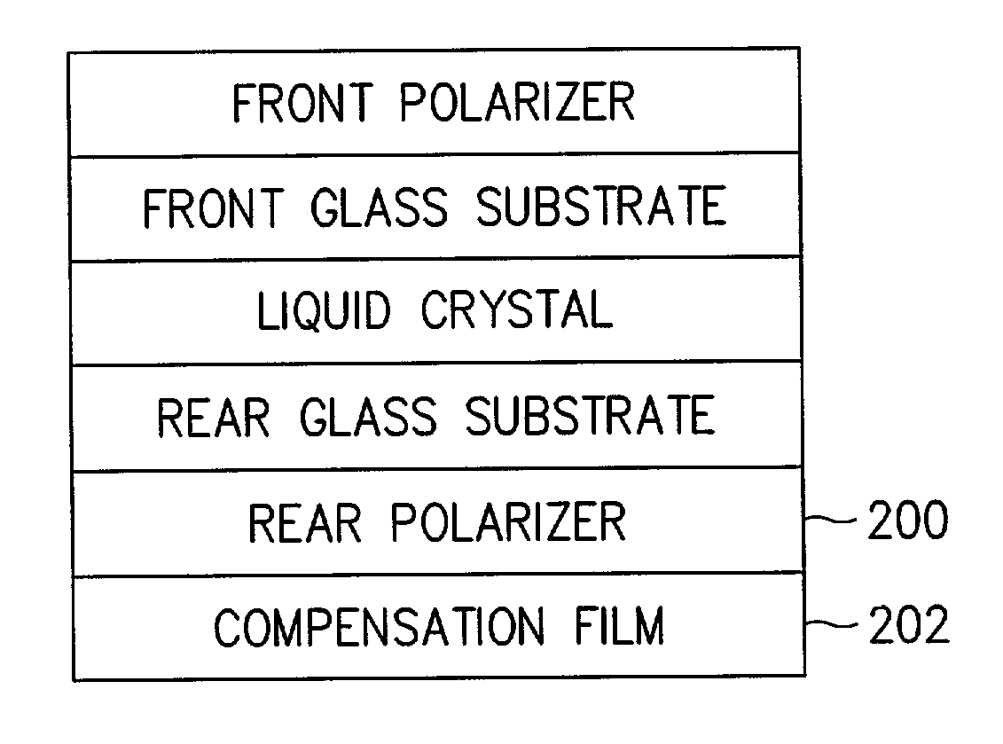
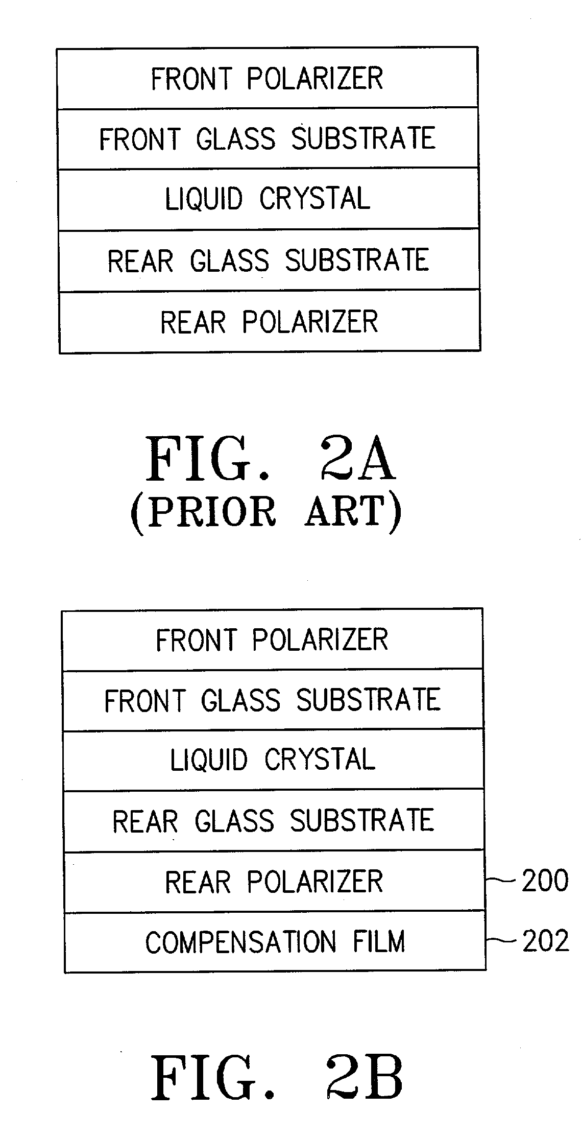
[0009]In order to obtain the foregoing object, the present invention is characterized in that a thin flexible reflective polarizing film capable of obtaining luminance elevation while maintaining an angular field adopted in a rear polarizer of an LCD in a portable terminal to function as a mirror by reflecting an external light typically when the LCD is powered off. Power supply to the portable terminal is on / off controlled which typically also powers on / off the LCD. Alternatively, a function key is provided for powering on / off the LCD to allow a user to immediately operate the LCD as a mirror.

Problems solved by technology

However, due to consumer demand and competition among providers, the portable terminal is required to provide various added functions.
However, the portable terminal fitted with the mirror or reflector has inconveniences of volume increase, design restriction and increase risk of breakage since typically only a common mirror or reflector is attached to one side of the portable terminal body.

Method used


Image

  • Apparatus and method for performing a mirror function in a portable terminal
  • Apparatus and method for performing a mirror function in a portable terminal
  • Apparatus and method for performing a mirror function in a portable terminal

Examples


Embodiment Construction

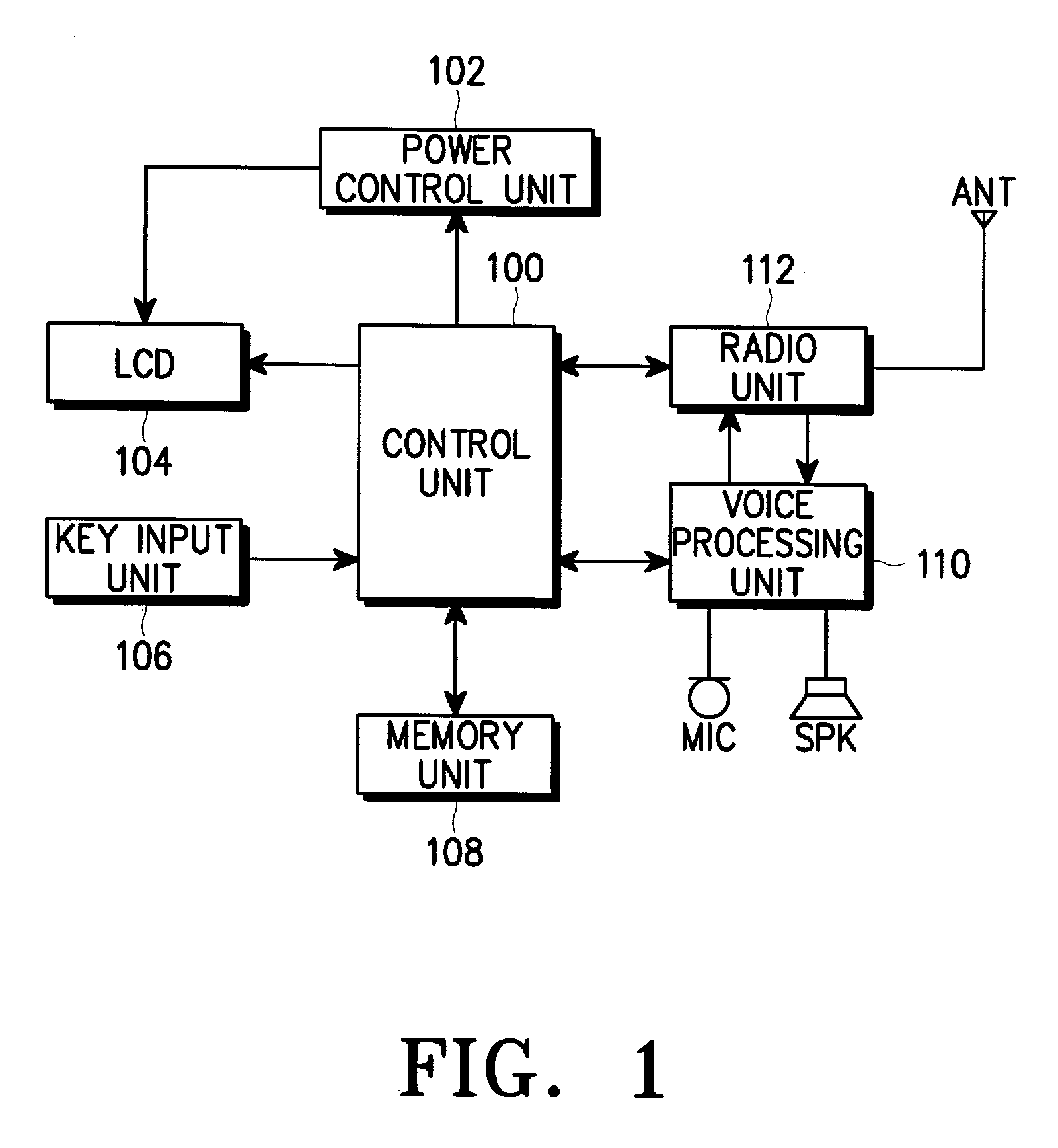
[0015]The following detailed description of a preferred embodiment of the invention will be made in reference to the accompanying drawings. In describing the invention, explanation about related functions or constructions which are known to the art will be omitted for the sake of clearness in understanding the concept of the invention. The following preferred embodiments of the present invention will be described with reference to the accompanying drawings. FIG. 1 is a block diagram of a portable terminal according to the embodiment of the invention, in which a radio unit 112 executes an operation for processing radio signals received from or transmitted to an external base station via an antenna ANT. For example, when an external call is received, the radio signal of call receipt is received through the radio unit 112, and then transferred to a control unit 100 to generate ring or execute several operations related to conversation.

[0016]A voice processing unit 110, under the contro...


PUM

PropertyMeasurementUnit
poweraaaaaaaaaa
timeaaaaaaaaaa
electric fieldaaaaaaaaaa

Abstract

Disclosed is an apparatus and method for embodying mirror function in a portable terminal by which a user can use an LCD of the portable terminal as a mirror, with a rear polarizer of the LCD constructed to allow the LCD to reflect incident light and to perform as a mirror when powered off, and to perform the original function of LCD when powered on. The LCD may further comprise a front polarizer for polarizing the external incident light to a certain direction, a liquid crystal for deflecting the incident light from the front polarizer about a molecular axis in the liquid crystal and arraying the light parallel to the direction of an electric field to pass the light along the molecular axis, and a rear polarizer for reflecting incident light from the liquid crystal when power is not applied and allowing the incident light to pass by the liquid crystal when power is applied.

Description

PRIORITY[0001]This application claims priority to an application entitled APPARATUS AND METHOD FOR EMBODYING MIRROR FUNCTION IN PORTABLE TERMINAL AND LIQUID CRYSTAL DISPLAY THEREFOR filed in the Korean Industrial Property Office on May 12, 2001 and assigned Serial No. 2001-26031, the contents of which are hereby incorporated by reference.BACKGROUND OF THE INVENTION[0002]1. Field of the Invention[0003]The present invention relates to a display device of a portable terminal, and more particularly, to an apparatus and method for embodying a mirror function in a portable terminal which enables a Liquid Crystal Display (LCD) of the portable terminal to be used as a mirror, and the LCD therefor.[0004]2. Description of the Related Art[0005]In general, a portable terminal has been proposed to provide a voice conversation service and / or a personal information service as main functions. However, due to consumer demand and competition among providers, the portable terminal is required to provi...

Claims


Application Information

Patent Timeline
Patent Type & Authority Patents(United States)
IPC IPC(8): G09G3/36G02F1/1335H04B1/38
CPCG02F1/133536G02F2001/133545G02F1/133545H04B1/40
Inventor KIM, JONG-MYUNGJUNG, JAE-IK
Owner SAMSUNG ELECTRONICS CO LTD
Learn More