Coordinates input apparatus

a technology of input apparatus and input device, which is applied in the direction of mechanical control device, manual control with single controlling member, instruments, etc., can solve the problems of limited extent to which the pointing device as a whole can be used, the overall size of the conventional pointing device is increased, and the space is little or no in which to operate the pointing device such as the mouse or the digitizer

Inactive Publication Date: 2006-12-19
FUJITSU TAKAMIZAWA COMPONENT LTD
View PDF27 Cites 23 Cited by
  • Summary
  • Abstract
  • Description
  • Claims
  • Application Information

AI Technical Summary

Benefits of technology

[0024]According to this aspect of the invention, the need for an impelling mechanism such as a coil spring of the conventional art is eliminated, thereby providing a simplified, more compact two-dimensional (X,Y) coordinates input apparatus.

Problems solved by technology

As a result, there is often little or no space in which to operate a pointing device such as a mouse or digitizer.
However, the conventional pointing device as described above has a disadvantage in that the restorative force of a compressed coil spring 3b is employed to return the key top 2a to its original position after it has been tilted in a given direction, with the result that the overall size of the conventional pointing device is increased at least by an amount equivalent to that portion of the coil spring 3b that engages the key top 2a, thus limiting the extent to which the pointing device as a whole, and in particular the key top 2a, can be reduced in size and made more compact.

Method used


Image

  • Coordinates input apparatus
  • Coordinates input apparatus
  • Coordinates input apparatus

Examples


first embodiment

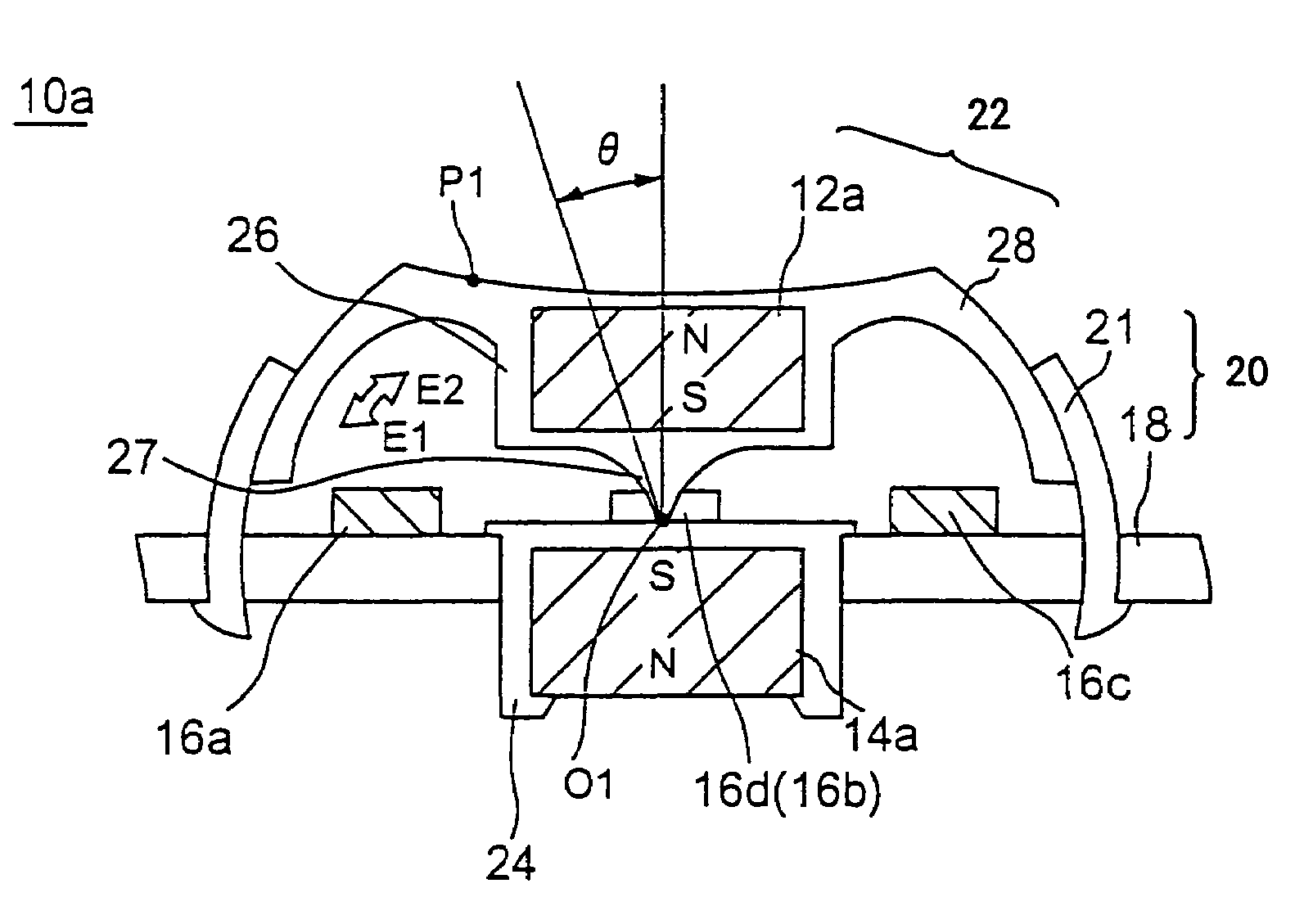
[0059]A description will now be given of a coordinates input apparatus according to the present invention, with reference to FIG. 7 and FIG. 8.

[0060]FIG. 7 is a front cross-sectional view of a coordinates input apparatus according to a first embodiment of the present invention. FIG. 8 is a graph showing differential output characteristics of the coordinates input apparatus according to the first embodiment of the present invention.

[0061]As shown in FIG. 7, the coordinates input apparatus 10a comprises essentially a housing 20 that includes a holder 21 and a circuit board 18, an operating part 22 that includes a second magnet 12a and a slider 28, magnetoelectric transducers 16a, 16b, 16c and 16d and a substantially cylindrical first magnet 14a.

[0062]The container 20, as noted above, contains a holder 21 having a curved surface and which extends vertically in FIG. 7. The circuit board 18 is substantially horizontal, and forms the bottom surface of the housing 20. The holder 21 and th...

second embodiment

[0072]A description will now be given of a coordinates input apparatus according to the present invention, with reference to FIG. 9, FIG. 10 and FIG. 11.

[0073]FIG. 9 is a front cross-sectional view of a coordinates input apparatus according to a second embodiment of the present invention. FIG. 10 is a graph showing differential output characteristics in the X(Y) directions of the coordinates input apparatus according to the second embodiment of the present invention. FIG. 11 is a graph showing differential output characteristics in the Z direction of the coordinates input apparatus according to the second embodiment of the present invention.

[0074]As can be appreciated from FIG. 9, the coordinates input apparatus 10b has essentially the same basic structure as the coordinates input apparatus 10a according to the first embodiment of the present invention as described above, the only substantive difference between the two embodiments being the coordinates input apparatus 10b according ...

third embodiment

[0082]A description will now be given of a coordinates input apparatus according to the present invention, with reference to FIG. 12 and FIG. 13.

[0083]FIG. 12 is a front cross-sectional view of a coordinates input apparatus according to a third embodiment of the present invention. FIG. 13 is a graph showing differential output characteristics in the X(Y) directions of the coordinates input apparatus according to the third embodiment of the present invention.

[0084]As shown in FIG. 12, the coordinates input apparatus 10c has a basic structure that is essentially the same as that for coordinates input apparatuses 10a and 10b, comprising the housing 20, the operating part 22, the magnetoelectric transducers 16a, 16b, 16c and 16d and the magnet 14b. The housing 20 in turn comprises the circuit board 18 and the holder 21 with its curved surface.

[0085]A case 32 having a projection 30 on the top is fixedly attached to the circuit board 18 at a center of a top surface of the circuit board 18...


PUM


Abstract

An improved coordinates input apparatus for designating a particular set of coordinates in three-dimensional space has a substantially box-like frame, a first magnet, a second magnet, and a plurality of magnetoelectric transducers. The first magnet and second magnet are mounted on the frame and disposed so that sides thereof having identical magnetic poles are disposed opposite each other. The second magnet is disposed so as to be tiltable in response to a disposition of forces acting thereupon. The forces include a repulsive force arising between the first magnet and the second magnet and a pressing force exerted on the second magnet. The plurality of magnetoelectric transducers mounted on the frame opposite the second magnet and output voltage values that vary according to a change in a gap between the magnetoelectric transducers and the second magnet, such that the voltage values indicate a set of X,Y coordinates in two-dimensional space.

Description

CROSS REFERENCE TO RELATED APPLICATION[0001]The subject application is a continuation application of application Ser. No. 09 / 865,707 filed May 29, 2001 now U.S. Pat. No. 6,738,043 which is now allowed.BACKGROUND OF THE INVENTION[0002]1. Field of the Invention[0003]The present invention relates to a coordinates input apparatus, and more particularly, to an improved coordinates input apparatus having a simplified structure and that can be used without the need for extensive special operating space.[0004]2. Description of Related Art[0005]In recent years, easy-to-operate pointing devices such as the mouse or digitizer, have come to be widely used instead of keyboards as an input means for desktop computers and the like.[0006]For example, a mouse or a digitizer can be used with desktop computers and the like.[0007]However, the laptop and other portable computers that have become popular in recent years are often used outdoors, in vehicles, and so forth, that is, in locations where there...

Claims


Application Information

Patent Timeline
Patent Type & Authority Patents(United States)
IPC IPC(8): G09G5/00G06F3/041G05G9/047G06F3/033G06F3/0338H01H25/04
CPCG06F3/0338H01H25/041G05G2009/04755H01H2025/046H01H2221/04H01H2239/024
Inventor ENDO, MICHIKO
Owner FUJITSU TAKAMIZAWA COMPONENT LTD
Why Eureka
Try Eureka