Imaging tomography apparatus having an attached patient support with a movable backrest

a tomography apparatus and patient support technology, applied in the direction of instruments, patient positioning for diagnostics, applications, etc., can solve the problem of difficult and achieve the effect of improving the accessibility of injured or elderly patients and improving the access to the surgery region of the patien

Inactive Publication Date: 2006-12-19
SIEMENS AG
View PDF9 Cites 5 Cited by
  • Summary
  • Abstract
  • Description
  • Claims
  • Application Information

AI Technical Summary

Benefits of technology

[0006]An object of the invention to provide an imaging tomography apparatus that avoids the aforementioned disadvantages. In particular, such an imaging tomography apparatus should enable improved access to a surgery region of the patient. A further object of the invention is to provide such an imaging tomography apparatus that enables improved accessibility for injured or elderly patients at the patient bed.
[0007]This object is achieved in accordance with the invention by an imaging tomography apparatus having a patient bed with a pivotable backrest connected to a seat. The position of the patient accommodated on the patient bed can be changed by pivoting the backrest relative to the seat. This eases the accessibility to a surgical procedure region on the patient. In particular injured patients can be placed in a sitting position, which is more comfortable under the circumstances, until implementation of the scan.
[0008]The patient bed thus can be moved horizontally, accommodated on a mounting device attached on the data acquisition device. The patient bed in particular can be moved horizontally along a tunnel or tube axis of the scanner. This enables an in-and-out deployment of the patient accommodated on the patient bed in the data acquisition device. Attached on the mounting device, the patient bed can appropriately be pivoted on a y-axis proceeding perpendicularly to the tunnel or tube axis. This enables the production of slice images disposed at an angle through the body axis of the patient. Furthermore, the patient can be brought into an operating position that is optimal for the medical auxiliary personnel or the surgeon.
[0009]In an embodiment of the invention, the patient bed has a foot part connected with the seat such that the foot part can pivot relative to the seat. The three-part execution of the patient bed further increases the freedom for positioning the patient. Accessibility to a surgery area is further improved. Accessibility for the patient to the patient bed is further simplified, for example for handicapped patients.
[0010]In a further embodiment, the mounting device is attached to the measurement device such that it can move vertically. In a preferred embodiment the data acquisition device, together with the mounting device attached thereto, is movably attached to a base (pedestal). In comparison to known apparatuses, this embodiment allows lowering of the patient bed particularly far down in the vertical direction. This further eases the accessibility to the patient bed.

Problems solved by technology

A problem thus sometimes occurs that the surgery region of the patient is difficult to access for the medical auxiliary personnel or the surgeon.

Method used


Image

  • Imaging tomography apparatus having an attached patient support with a movable backrest
  • Imaging tomography apparatus having an attached patient support with a movable backrest
  • Imaging tomography apparatus having an attached patient support with a movable backrest

Examples


Embodiment Construction

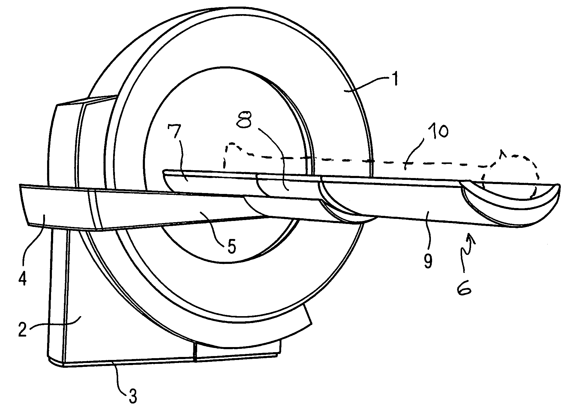
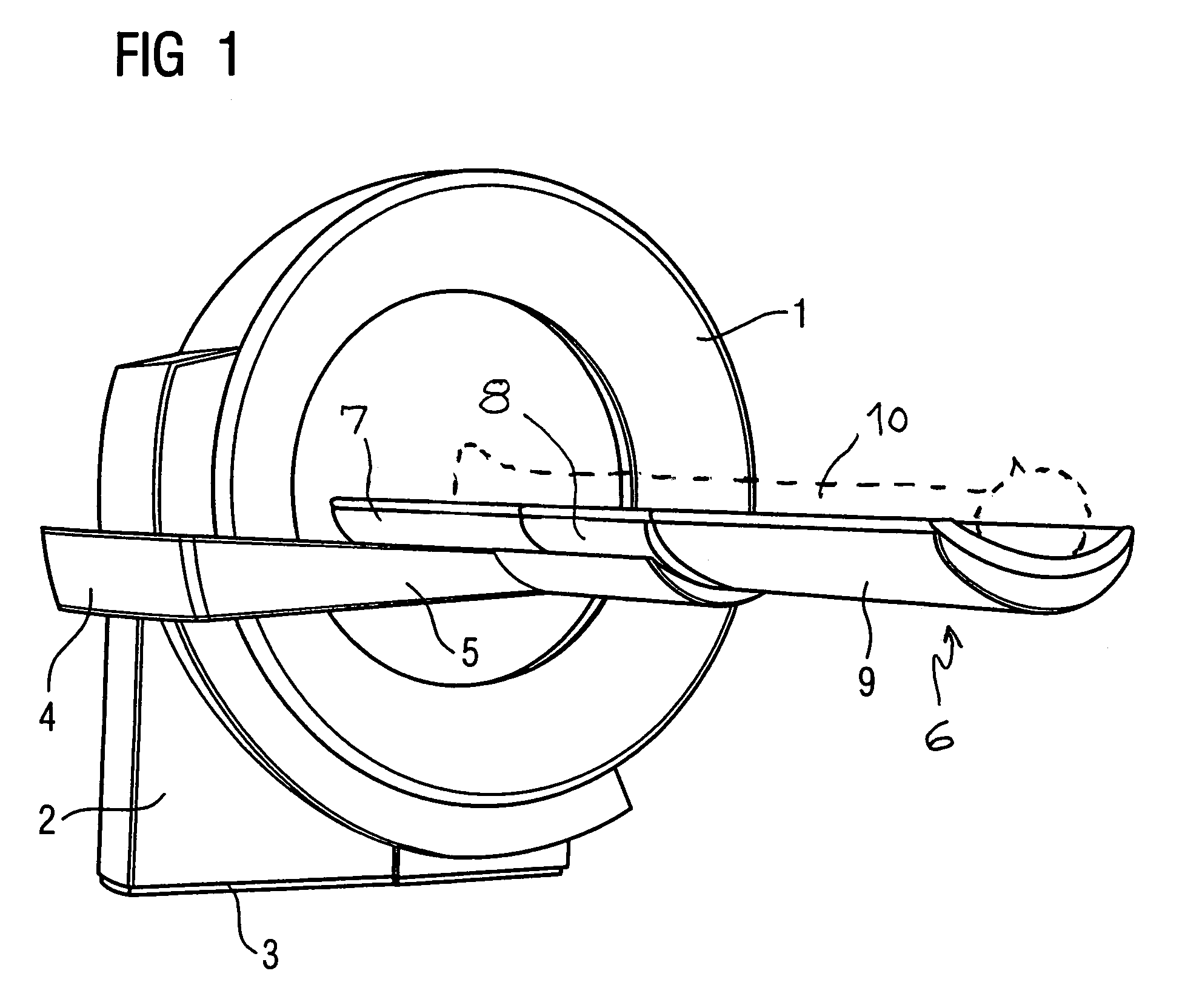
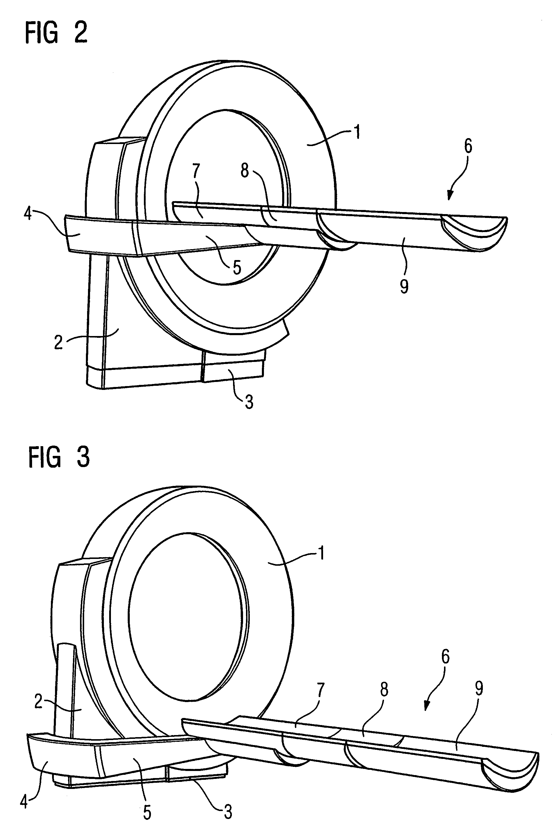
[0018]A tomography apparatus is shown in FIGS. 1 through 5 in the example of an x-ray computed tomography apparatus. An annularly fashioned data acquisition device or gantry 1 is accommodated on a carrier 2. The carrier 2 is supported on a base 3 such that the carrier 2 can be moved vertically. In addition, a hydraulically-operable or electrically-operable lifting device (not shown) is provided. A mounting device 4 that can be moved vertically is in turn attached to the carrier 2. A mounting arm 5 of the mounting device 4 accommodates a patient bed 6 such that it can move horizontally. The patient bed 6 can move horizontally, in particular parallel to the axis of the data acquisition device 1. As is best seen from FIG. 4, the patient bed 6 is formed of a backrest 7, a seat 8 and a foot part 9. For vertical movement of the mounting device 5, a further hydraulically-operable or electrically-operable lifting device (not shown) is provided. A preferably electrically-operable horizontal ...


PUM

PropertyMeasurementUnit
imaging tomographyaaaaaaaaaa
vertical movementaaaaaaaaaa
computed tomographyaaaaaaaaaa

Abstract

An imaging tomography apparatus, such as an x-ray computed tomography apparatus or a magnetic resonance tomography apparatus, has a patient bed that can be driven into a tunnel-shaped or annular data acquisition device. To increase comfort for the patient and accessibility by medical personnel, the patient bed has a pivotable backrest connected to a seat.

Description

BACKGROUND OF THE INVENTION[0001]1. Field of the Invention[0002]The present invention concerns an imaging tomography apparatus, in particular an x-ray computed tomography apparatus or magnetic resonance tomography apparatus of the type having a patient bed that is driven into and out of a data acquisition device (scanner).[0003]2. Description of the Prior Art[0004]X-ray computed tomography and magnetic resonance tomography systems are known as imaging tomography apparatuses or systems. A common feature of such tomography apparatuses is a tube-shaped or tunnel-shaped data acquisition device (scanner). For data acquisition, the patient is horizontally moved into the scanner on a patient bed mounted at the tomography apparatus. The patient bed also can be vertically movable. This makes it easer to place the patient on the patient bed or to disembark after the scan, in particular for injured or elderly patients.[0005]In practice, sometimes a procedure must be conducted on the patient fo...

Claims


Application Information

Patent Timeline
Patent Type & Authority Patents(United States)
IPC IPC(8): H05G1/60H05G1/00A61B5/055A61B6/00A61B6/03A61B6/04G01N23/00G21K1/12
CPCA61B6/04
Inventor MAIER, SEBASTIANTHORMANN, KLAUS
Owner SIEMENS AG
Why Eureka
Try Eureka