Air bag system

Inactive Publication Date: 2006-12-26
HONDA MOTOR CO LTD
View PDF7 Cites 38 Cited by
  • Summary
  • Abstract
  • Description
  • Claims
  • Application Information

AI Technical Summary

Benefits of technology

[0007]According to the construction that is described above, since the end portion of the restricting member disposed along the outer surface of the air bag is coupled to the retainer, the occupant can be restrained gently by restricting the axial inflation of the air bag by the restricting member in the earlier stage of deployment of the air bag, and in the later stage of deployment of the air bag, the brittle portion on the restricting member is broken by the tension applied to the restricting member so as to allow the air bag to inflate to its maximum capacity to thereby exhibit its maximum occupant restraining performance.
[0008]Moreover, since the vent hole in the air b

Problems solved by technology

In the event that the vent hole is constituted by a simple hole opened in the base fabric, since the gas leaks from the vent hole in a process where the air bag is inflated by the gas supplied from the inflator, there is a possibility that the deployment of the air bag will be delayed.
In

Method used


Image

  • Air bag system
  • Air bag system
  • Air bag system

Examples


first embodiment

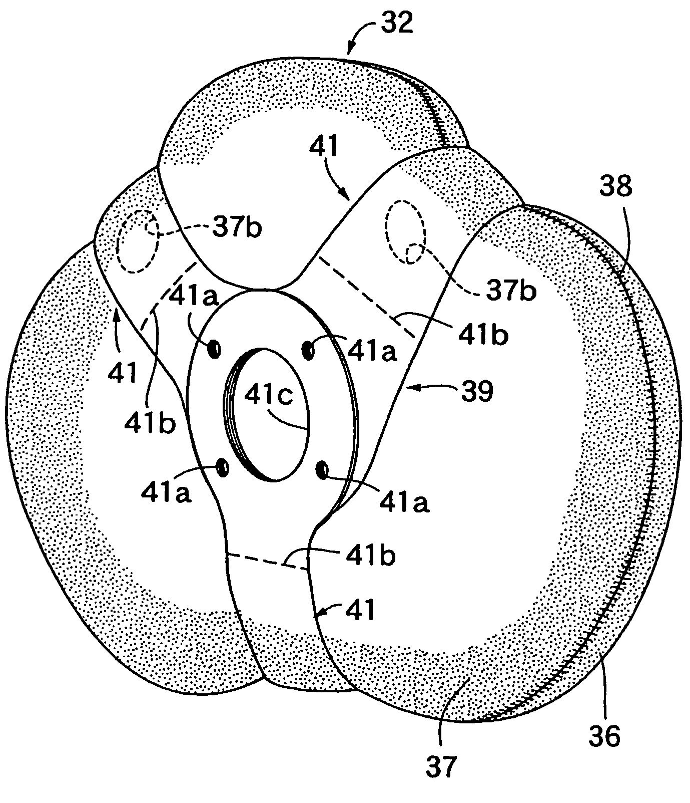
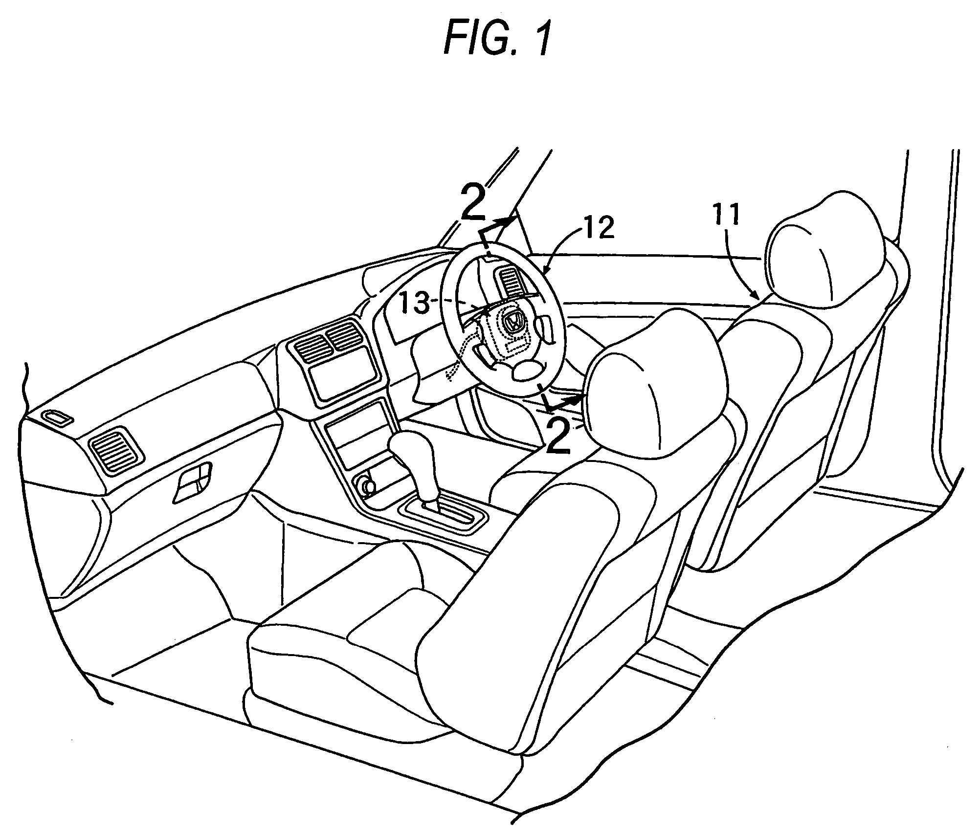
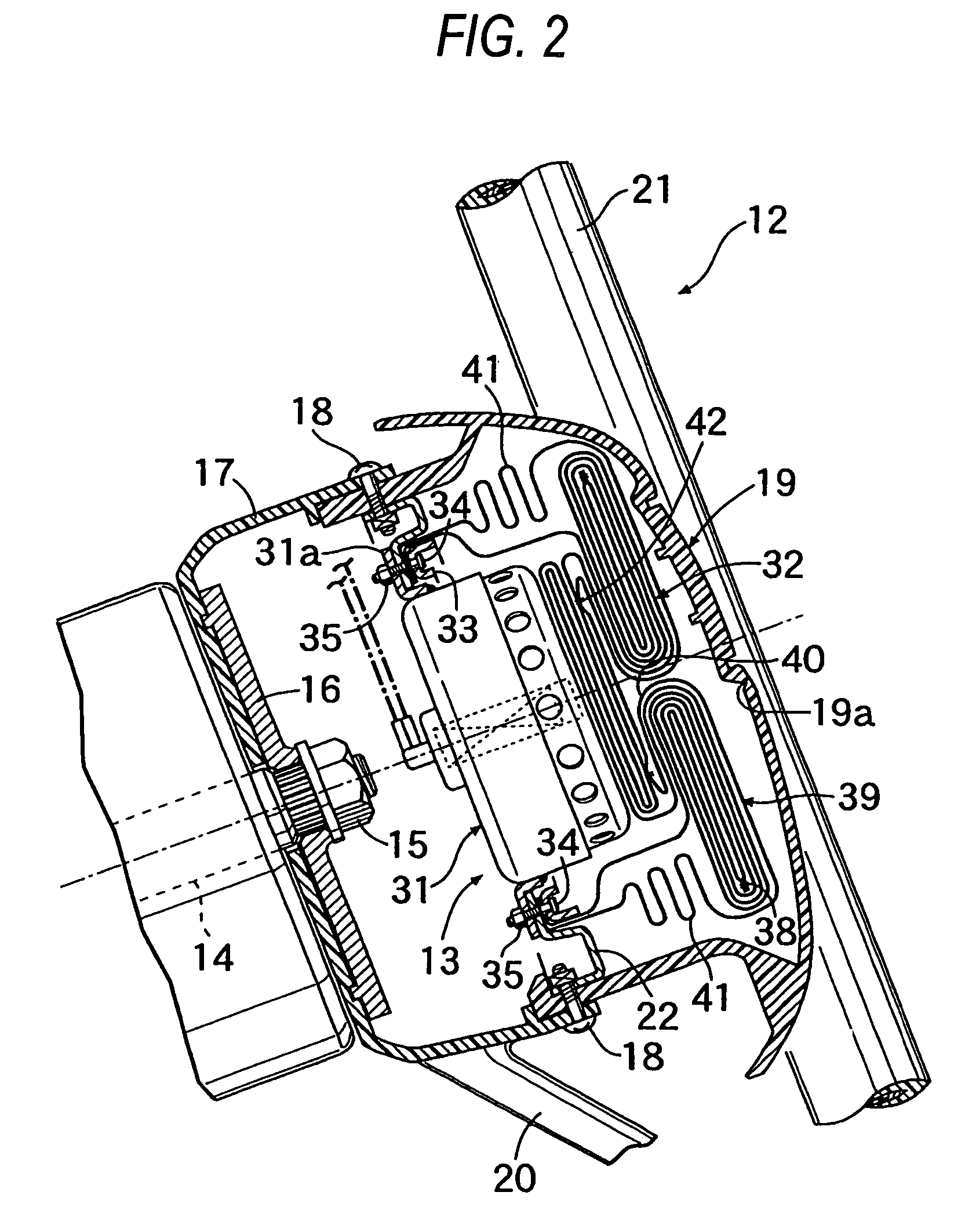
[0019]FIGS. 1 to 7 illustrates a first embodiment, in which FIG. 1 is a perspective view of a front part of a passenger compartment of an automobile, FIG. 2 is an enlarged cross-sectional view taken along the line 2—2 in FIG. 1, FIG. 3 an exploded perspective view of an air bag module, FIG. 4 is an exploded perspective view of an air bag, FIG. 5 is an explanatory drawing which explains the function of the air bag when it deploys (a view as seen in a direction indicated by an arrow 5 in FIG. 6), FIG. 6, is a view as seen in a direction indicated by an arrow 6 in FIG. 5, and FIG. 7 is an explanatory drawing explaining the function of the air bag when restricting fabrics are broken, which corresponds to FIG. 5.

[0020]As shown in FIG. 1, an air bag module 13 for a driver's seat 11 is accommodated in the interior: of a steering wheel 12 disposed in front of the driver's seat 11.

[0021]As shown in FIGS. 2 and 3, the steering wheel 12 includes a boss portion 16 fixed to a rear end of a steer...

second embodiment

[0030]Next, the invention will be described based on FIGS. 8 and 9.

[0031]While in the first embodiment the restricting member 39 has the four restricting fabrics 41 which extend radially at intervals of 90°, a restricting member 39 according to a second embodiment of the invention has three restricting fabrics 41 which extend radially at intervals of 120°. Circular openings 41c are formed in distal ends of the respective restricting fabrics 41 in such a manner as to be overlapped each other so as to be fixed to the fixing ring 33, and brittle portions 41b adapted to be broken in association with an increase in tension are formed in the vicinity of the openings 41c, respectively. Of the three restricting fabrics 41, the upper two restricting fabrics 41, 41 are disposed at positions where the vent holes 37b, 37b in the second base fabric 37 of the air bag 32 which is in a deployment process are closed.

[0032]Thus, a similar function and advantage to those attained in the first embodime...


PUM


Abstract

A restricting member 39 disposed along an outer surface of an air bag 32 restricts an axial inflation of the air bag 32 in an earlier stage of deployment of the air bag 32, and in a later stage of deployment, the restricting member 39 allows for the inflation of the air bag 32 to its maximum capacity through breakage of brittle portions 41b. In the deployment process of the air bag 32, since vent holes 37b formed in a base fabric 37 of the air bag 32 are closed by the restricting member 39, the leakage of gas from the vent holes 37b is prevented to thereby enable a quick deployment of the air bag 32. Then, when the brittle portions 41b on the restricting member 39 break, the vent holes 37b are opened.

Description

BACKGROUND OF THE INVENTION[0001]The present invention relates to an air bag system in which a folded air bag and an inflator are supported on a retainer, so that the air bag is inflated to be deployed into a passenger compartment of a vehicle by a gas produced by the inflator at the time of collision.[0002]An air bag adapted to be deployed into a passenger compartment of a vehicle by a gas supplied from an inflator at the time of collision of the vehicle is provided with a vent hole, and when an internal pressure of the inflating air bag increases as a result of restraining an occupant, the gas so supplied is then released through the vent hole so as to decrease the tension of abase fabric of the air bag, whereby not only is the occupant restrained gently but also the breakage of the base fabric is prevented.[0003]In the event that the vent hole is constituted by a simple hole opened in the base fabric, since the gas leaks from the vent hole in a process where the air bag is inflat...

Claims


Application Information

Patent Timeline
IPC IPC(8): B60R21/239B60R21/16B60R21/203B60R21/233B60R21/2338
CPCB60R21/203B60R21/2338B60R21/239B60R2021/23386
Inventor KAI, TAKESHI
Owner HONDA MOTOR CO LTD
Why Eureka
Try Eureka