
Push latch

a technology of push-type latches and latches, which is applied in the direction of mechanical devices, furniture parts, carpet fasteners, etc., can solve the problems of affecting the overall utility of the latch, the magnetic catch of the latch in general, and the deficiency of bisbing, so as to achieve the effect of only providing a finite amount of holding for

Active Publication Date: 2006-12-26
ACTON MFG
View PDF18 Cites 48 Cited by
  • Summary
  • Abstract
  • Description
  • Claims
  • Application Information

AI Technical Summary

Benefits of technology

"The patent describes a push-to-open latch that can be used as a hidden door latch or a stowable coat hook. The latch is mounted inside a cabinet and is not visible on the exterior surface. The latch has a dowel rod assembly and a catch assembly with inner and outer cams that rotate to engage or disengage the latch. The latch can be moved between locked and unlocked positions by pushing the push-to-open latch. The technical effect of this invention is that it provides a simple and effective mechanism for opening and closing doors or accessories without the need for additional hardware or protruding parts."

Problems solved by technology

Although the magnetic catch of the Bisbing reference is configured in such a manner as to avoid misalignment of the magnet during subsequent closing of the door, magnetic catches of the type disclosed in Bisbing suffer from several deficiencies that detract from their overall utility.
Furthermore, the magnetic catch of Bisbing as well as magnetic latches in general typically can provide only a finite amount of holding force.
Under such conditions, magnetic catches may be incapable of withstanding opening forces acting against an inner surface of a cabinet door due to shifting contents or luggage inside the cabinet.
Louis reference may unfortunately result in asymmetric or eccentric loading on individual components which may limit the operating life of the latch system.
Such cantilevered mounting may result in the inducement of excessive bending forces within the lever at the pin attachment point should a user attempt to improperly open the door by pulling outwardly, as is more intuitive, that by pushing inwardly as is required to open the door.
Even if outward pulling on the door does not initially damage the latch system, the eccentric loads induced on the lever under repeated attempts to open the door may cause the lever to bend so that, eventually, the pin may jam within the groove.

Method used


Image

  • Push latch
  • Push latch
  • Push latch

Examples


Embodiment Construction

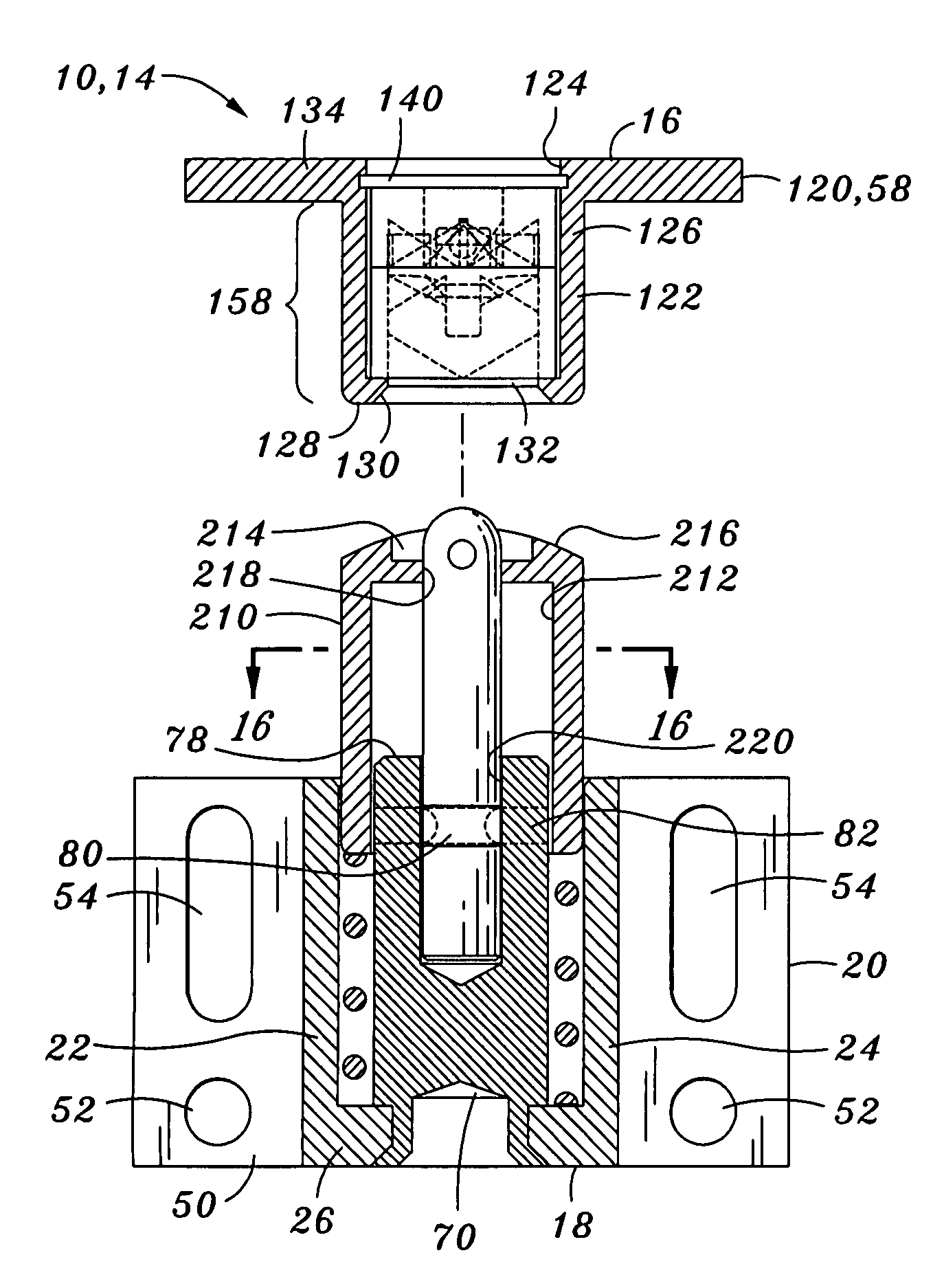
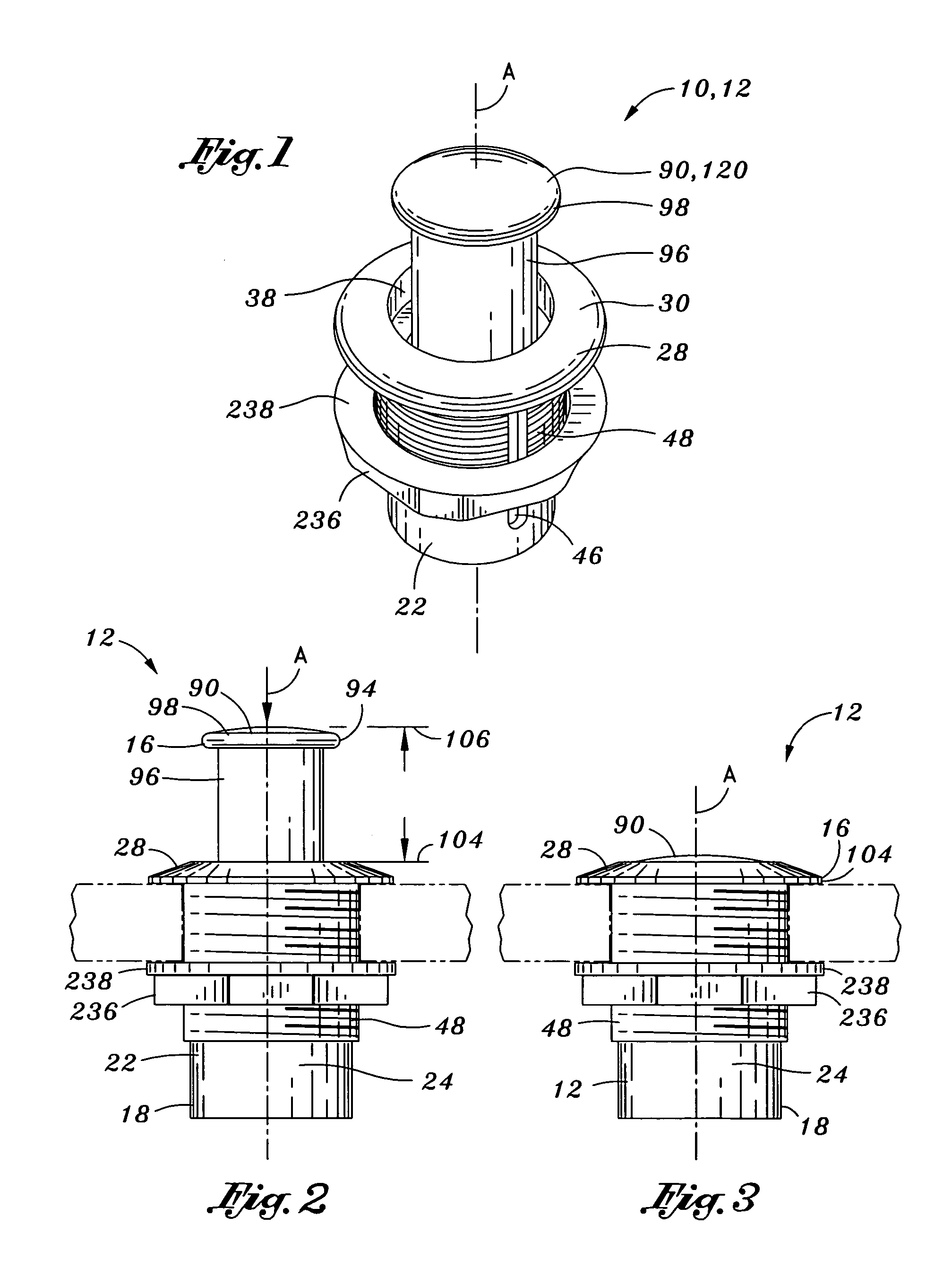
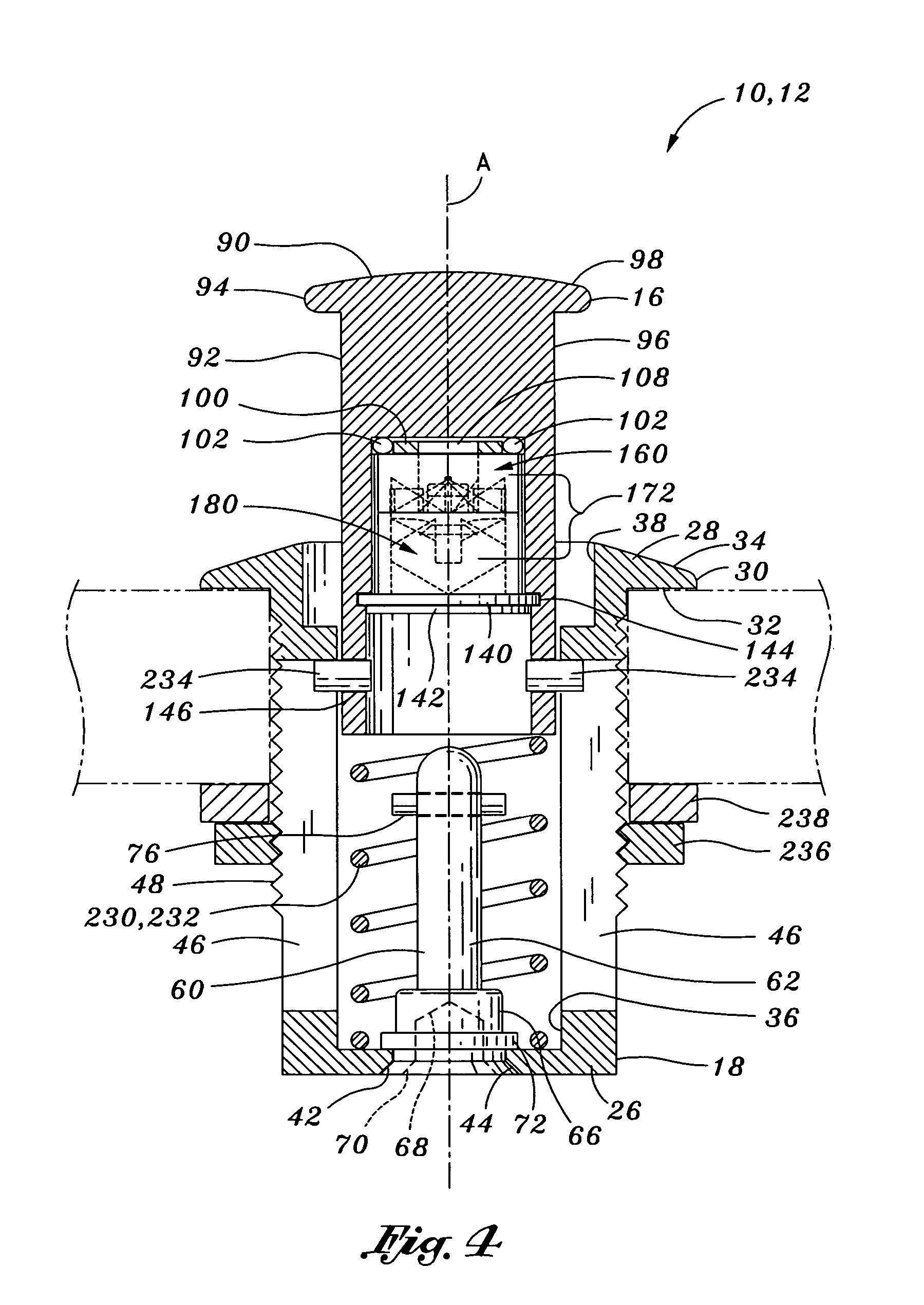
[0040]Referring now to the drawings wherein the showings are for purposes of illustrating the present invention and not for purposes of limiting the same, shown in FIGS. 1–20 is a push-to-open latch 10 that is adapted for use as a hidden door latch 14 (FIGS. 15–20) or a stowable coat hook 12 (FIGS. 1–4) which are respectively latchable / unlatchable or stowable / extendable in response to an external force applied thereto due to the cooperative engagement of a dowel rod assembly 60 with a uniquely configured cam mechanism 158. In the door latch 14 embodiment, the push-to-open latch 10 is mountable within a cabinet such that no latch hardware is visible on exterior surfaces of the cabinet, as shown in FIGS. 19 and 20. In the coat hook 12 embodiment, the push-to-open latch 10 is selectively moveable between stowed and extended positions 104, 106 as shown in FIGS. 2–3.

[0041]As best seen in FIG. 3, in the stowed position 104, the coat hook 12 may be configured to be substantially flush with...


PUM


Abstract

A push-to-open latch is selectively moveable between latched and unlatched positions. The push-to-open latch comprises a latch assembly that is reciprocatable relative to a catch assembly. The latch assembly includes a latch housing having a housing bore extending to a housing bottom wall. A pin rod shaft extends upwardly from the housing bottom wall and has a pin rod dowel extending outwardly therefrom. The catch assembly includes a catch housing with an inner and outer cam rotatably disposed therewithin and having mating ends that collectively define a cam interior. The inner and outer cam mating ends have cam bores and inner and outer cam mating end ramps that cooperate to alternately engage and release the pin rod dowel from the cam interior such that the latch is respectively placed in the latched and unlatched positions during reciprocation of the pin rod shaft through the cam bore.

Description

CROSS-REFERENCE TO RELATED APPLICATIONS[0001]Not ApplicableSTATEMENT RE: FEDERALLY SPONSORED RESEARCH / DEVELOPMENT[0002]Not ApplicableBACKGROUND OF THE INVENTION[0003]The present invention relates generally to mechanical latching mechanisms and, more particularly, to a uniquely configured push-to-open latch that may be adapted for use as a hidden door latch or a stowable coat hook which are respectively latchable or stowable in response to an external force applied thereto.[0004]In attempts to improve the appearance of interiors such as aircraft interiors as well as to reduce the hazards posed by protrusions such as cabinet handles in such interiors, several prior art latches have been developed wherein the latch is hidden from view. Such latches may be used in applications wherein a door or drawer is latchable to a cabinet or a bin, etc. Prior art latches have included both mechanical and magnetic means to maintain the door in a closed or latched position.[0005]For example, U.S. Let...

Claims


Application Information

Patent Timeline
Patent Type & Authority Patents(United States)
IPC IPC(8): E05C19/00E05B15/02
CPCA47G25/065B60R7/10E05C19/022Y10S292/04Y10S292/15Y10S292/37A47B88/463Y10T292/68Y10T292/42Y10T292/444
Inventor RECHBERG, FRANK H.
Owner ACTON MFG
Learn More