Laryngoscope for simultaneously facilitating the illuminating of a throat pathway and inserting an intubation tube

a technology of a laryngoscope and a throat pathway, which is applied in the field of laryngoscope, can solve the problems of difficulty, inability to determine the examination of the larynx, and the insufficient lifting of the epiglottis to expose the larynx

Active Publication Date: 2006-12-26
GIRGIS MAGDY S
View PDF13 Cites 35 Cited by
  • Summary
  • Abstract
  • Description
  • Claims
  • Application Information

AI Technical Summary

Benefits of technology

[0018]ACCORDINGLY, AN OBJECT of the present invention is to provide a laryngoscope for simultaneously spreading the epiglottis and the posterior tissue defin

Problems solved by technology

With a small fraction of patients, the epiglottis will not be lifted sufficiently to expose the larynx in the usual laryngoscopic procedures.
Unfortunately, the small percentage of patients having the anatomical structure which makes the examination of the larynx difficult cannot be determined by visually examining the epiglottis before inserting the laryngoscope.
Usually, it is not until the anesthesiologist tries to expose the larynx to administer anesthetic g

Method used


Image

  • Laryngoscope for simultaneously facilitating the illuminating of a throat pathway and inserting an intubation tube
  • Laryngoscope for simultaneously facilitating the illuminating of a throat pathway and inserting an intubation tube
  • Laryngoscope for simultaneously facilitating the illuminating of a throat pathway and inserting an intubation tube

Examples


Embodiment Construction

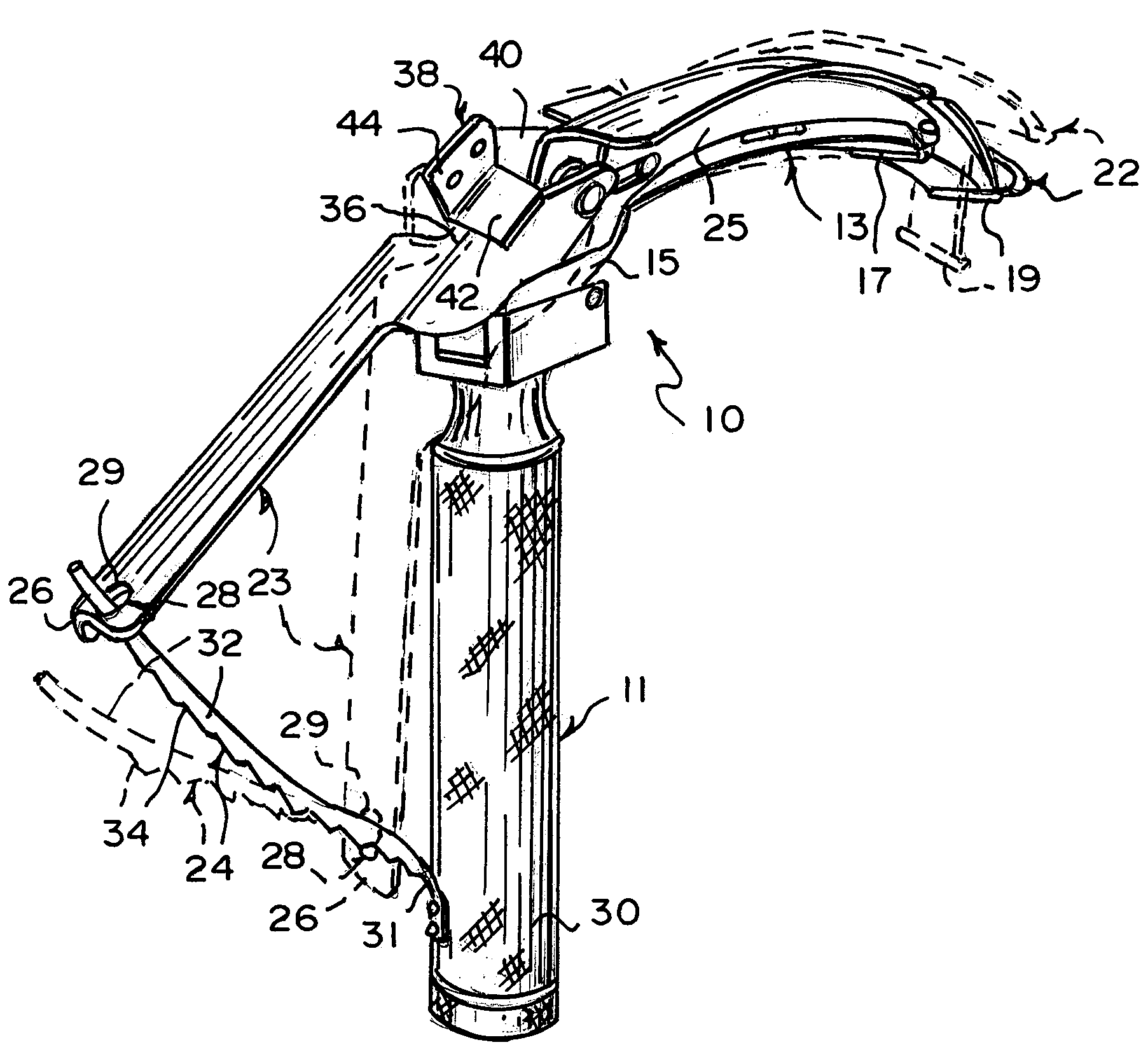
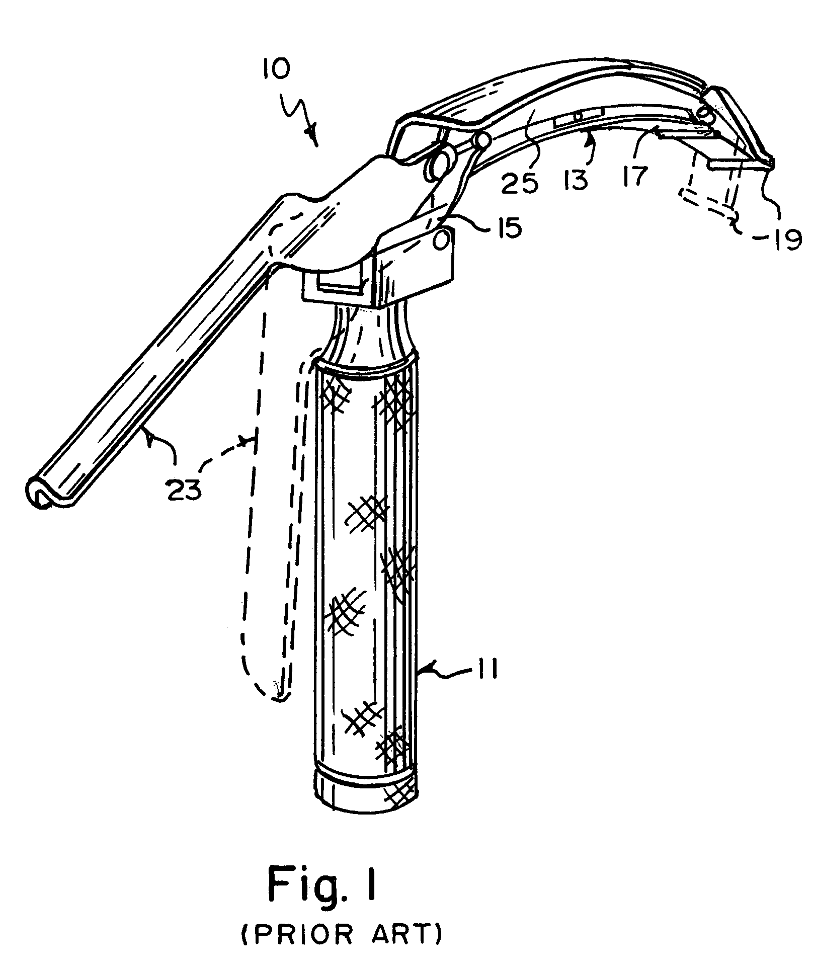
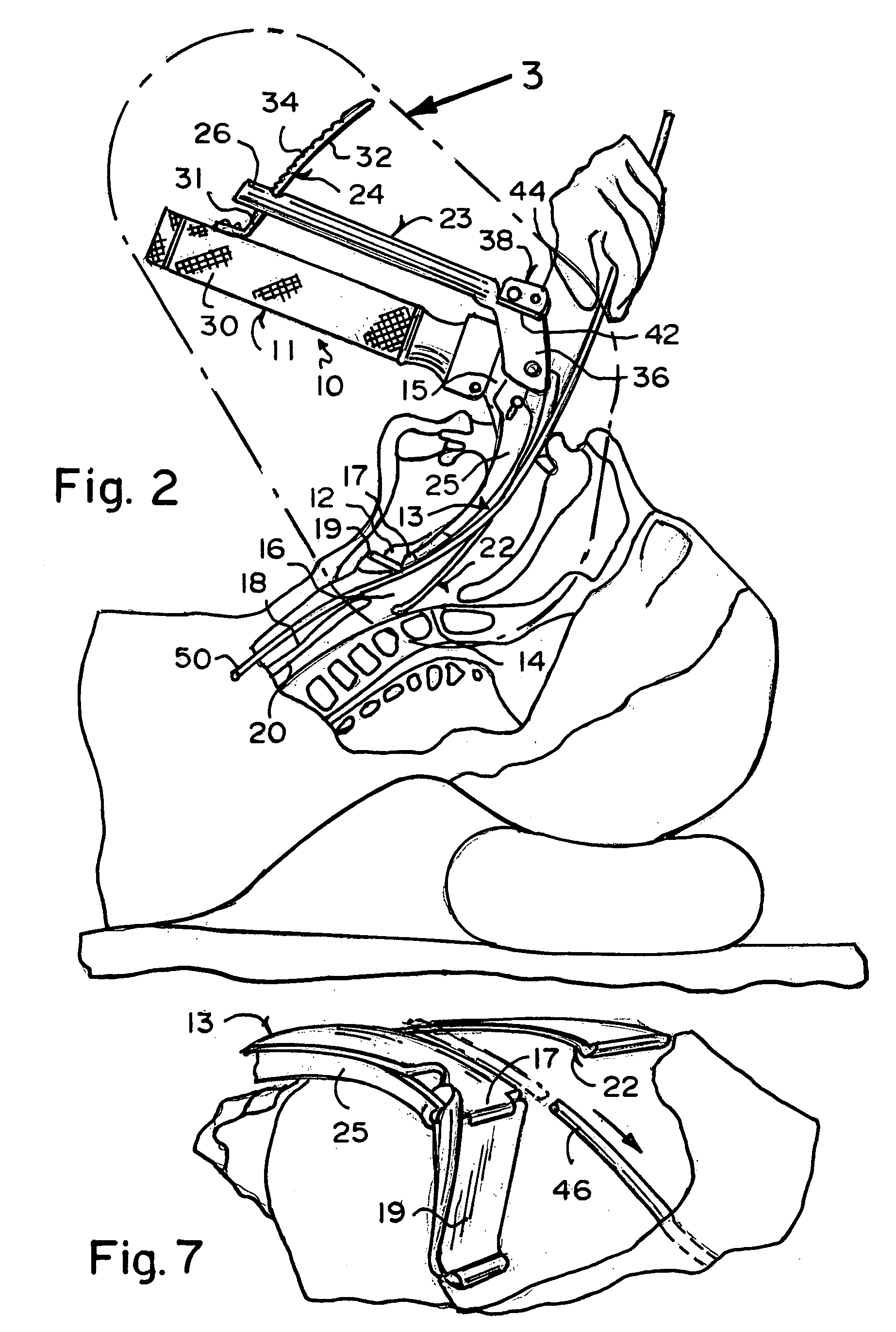
[0061]Referring now to the figures, in which like numerals indicate like parts, and particularly to FIG. 2, the laryngoscope of the present invention is shown generally at 10 for simultaneously spreading the epiglottis 12 and the posterior tissue 14 defining the superior opening 16 of the larynx 18 away from each other for opening up the trachea 20 and exposing the larynx 18.

[0062]The configuration of the laryngoscope 10 can best be seen in FIGS. 3–8, and as such, will be discussed with reference thereto.

[0063]The laryngoscope 10 comprises a movable blade 22. The movable blade 22 is pivotally attached to the stationary blade 13 and affixed to the movable handle 23 for movement therewith so as to allow the movable blade 22 to pivot away from the stationary blade 13 when the movable handle 23 is moved towards the stationary handle 11 for spreading the posterior tissue 14 defining the superior opening 16 of the larynx 18 away from the epiglottis 12 as the tip 19 depresses the epiglotti...


PUM


Abstract

An improved laryngoscope of the type having a stationary handle, a stationary blade affixed to the stationary handle, a tip pivotally attached to the stationary blade, a movable handle pivotally attached to the stationary blade, and an arm pivoting the tip downwardly when the movable handle is moved towards the stationary handle depressing the epiglottis. The improvement includes a movable blade pivotally attached to the stationary blade and affixed to the movable handle so as to allow the movable blade to pivot away from the stationary blade when the movable handle is moved towards the stationary handle and spread the posterior tissue defining the superior opening of the larynx away from the epiglottis simultaneously as the tip depresses the epiglottis and both thereby opening up the trachea exposing the larynx, and a lock locking the movable blade in a desired positioned by locking the movable handle affixed thereto.

Description

BACKGROUND OF THE INVENTION[0001]1. Field of the Invention[0002]The present invention relates to a laryngoscope. More particularly, the present invention relates to a laryngoscope for simultaneously spreading the epiglottis and the posterior tissue defining the superior opening of the larynx away from each other for opening up the trachea and exposing the larynx.[0003]2. Description of the Prior Art[0004]Laryngoscopes generally comprise a blade and a cooperating, detachable handle which are connected together into an L-shaped configuration. When using the device to view the larynx, the surface on the blade adjacent the handle is used to press against the tongue and mandible of a patient in a supine position in order to prevent the patient's tongue from obstructing the view during the visual examination. While the instrument is useful in examining the larynx, the primary function of the laryngoscope is to expose the larynx in order to facilitate the insertion of an endotracheal tube ...

Claims


Application Information

Patent Timeline
IPC IPC(8): A61B1/267
CPCA61B1/267
Inventor GIRGIS, MAGDY S
Owner GIRGIS MAGDY S
Why Eureka
Try Eureka