System for efficiently cooling a processor

a processor and efficient technology, applied in the field of system for efficiently cooling a processor, can solve the problems of increasing airflow through the disclosed cooling system, and achieve the effects of improving the heat transfer efficiency of the disclosed system, increasing airflow, and increasing heat transfer area

Active Publication Date: 2006-12-26
NVIDIA CORP
View PDF7 Cites 28 Cited by
  • Summary
  • Abstract
  • Description
  • Claims
  • Application Information

AI Technical Summary

Benefits of technology

[0011]One advantage of the disclosed cooling system is that it uses the system fan of a computing device to draw air through the heat exchanger, thereby eliminating the need for a dedicated fan. Further, using the system fan, as opposed to a dedicated fan, also increases airflow through the disclosed cooling system. This, combined with an increased heat transfer area, substantially improves the heat transfer effectiveness of the disclosed system.

Problems solved by technology

Further, using the system fan, as opposed to a dedicated fan, also increases airflow through the disclosed cooling system.

Method used


Image

  • System for efficiently cooling a processor
  • System for efficiently cooling a processor
  • System for efficiently cooling a processor

Examples


Embodiment Construction

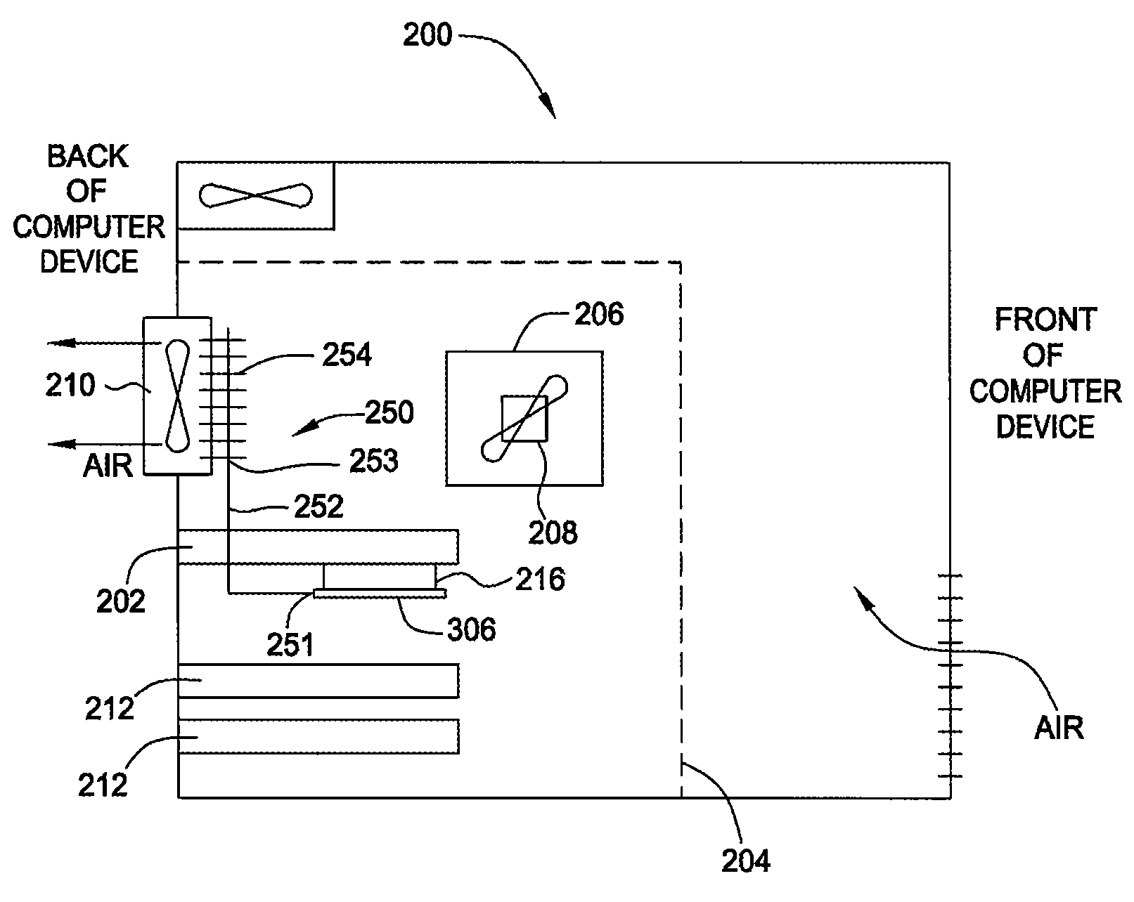
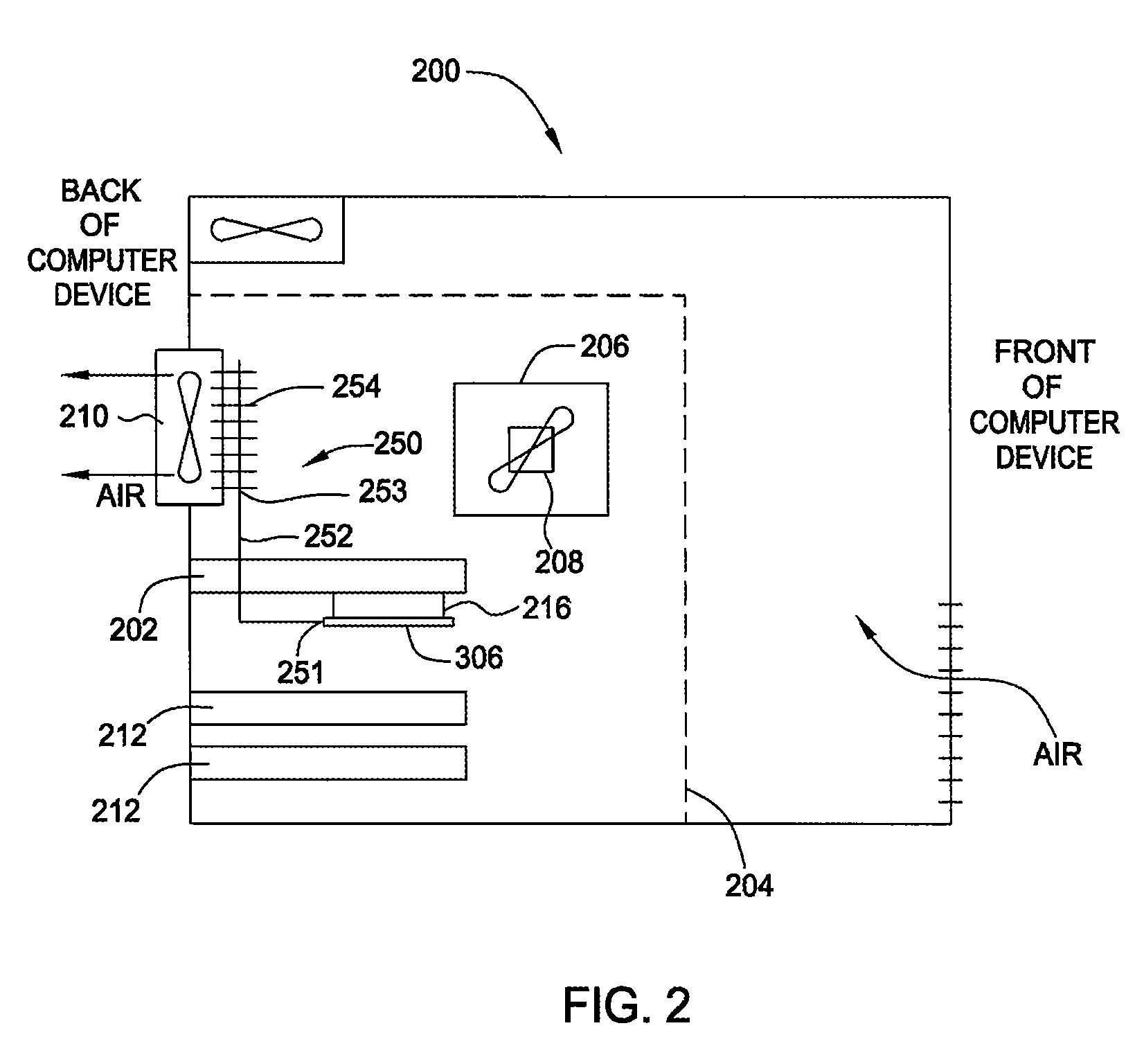
[0015]FIG. 2 is a schematic diagram illustrating a computing device 200, within which an improved cooling system 250 for cooling a graphics processing unit (GPU) 216 is incorporated, according to one embodiment of the present invention. Computing device 200 may be any type of computing device, including, without limitation, a desktop computer, server, laptop computer, palm-sized computer, personal digital assistant, tablet computer, game console, cellular telephone, computer-based simulator and the like.

[0016]Generally, cooling system 250 is configured to be coupled to GPU 216 in lieu of a conventional cooling system, such as cooling system 118 of FIG. 1, and includes, without limitation, a mounting plate (not shown), a passive heat transport device 252 and a heat exchanger 254. Passive heat transport device 252 is coupled at a first end 251 to GPU 216 and is adapted to extend away from GPU 216 in a direction toward system fan 210. As described in further detail below in conjunction...


PUM


Abstract

One embodiment of a system for efficiently cooling a processor includes a mounting plate configured to be thermally coupled to the processor, a passive heat transport device thermally coupled to the mounting plate and a heat exchanger coupled to the passive heat transport device.

Description

BACKGROUND OF THE INVENTION[0001]1. Field of the Invention[0002]This invention relates generally to computer hardware and relates more particularly to a system for efficiently cooling a processor.[0003]2. Description of the Background Art[0004]FIG. 1 is a schematic diagram illustrating a computing device 100, within which a conventional cooling system 118 for cooling a graphics processing unit (GPU) 116 is incorporated. As shown, computing device 100 includes a housing 101, within which a motherboard 104 resides. Mounted on motherboard 104 are a central processing unit (CPU) 106, a processor cooler 108 for cooling CPU 106, a system fan 110 for removing heat from computing device 100 and one or more peripheral component interface (PCI) cards 112, each interfaced with a slot located in the back part of housing 101. Motherboard 104 further incorporates a graphics card 102 that enables computing device 100 to rapidly process graphics related data for graphics intensive applications such...

Claims


Application Information

Patent Timeline
Patent Type & Authority Patents(United States)
IPC IPC(8): H05K7/20F28D15/00G06F1/20H05K5/00
CPCG06F1/20H05K7/20809G06F2200/201
Inventor STEFANOSKI, ZORANKIM, JEONG H.
Owner NVIDIA CORP
Why Eureka
Try Eureka