Through-timing of data transmitted across an optical communications system utilizing frequency division multiplexing

a technology of optical communication system and data transmission rate, applied in the field of maintaining the timing of data transmitted across optical communication system, can solve the problems of reducing data transmission rate, increasing the demand, and requiring longer timeslots, so as to remove unwanted jitter

Inactive Publication Date: 2006-12-26
FAR NORTH PATENTS LLC
View PDF36 Cites 23 Cited by
  • Summary
  • Abstract
  • Description
  • Claims
  • Application Information

AI Technical Summary

Benefits of technology

[0018]Transmitting and receiving data as described above is advantageous since the entire system is transparent for jitter tolerance purposes. In other words, if the incoming tributary meets the jitter tolerance, then the outgoing tribut

Problems solved by technology

Upcoming widespread deployment of new bandwidth-intensive services, such as xDSL, will only further intensify this demand.
Loose jitter tolerances will result in longer timeslots required for each bit which, in turn, will mean lower data transmission rates.
As a result, the number of different optical carriers is limited and if each carrier corresponds to a low-speed channel, as is typically the case, the total number of low-speed channels is also limited.
This typically is a drawback since, for example, many data streams occur at a much lower bit rate, such as at 155 Megabits per second (Mbps) for OC-3, and will underutilize the higher data rate specified for each

Method used


Image

  • Through-timing of data transmitted across an optical communications system utilizing frequency division multiplexing
  • Through-timing of data transmitted across an optical communications system utilizing frequency division multiplexing
  • Through-timing of data transmitted across an optical communications system utilizing frequency division multiplexing

Examples


Embodiment Construction

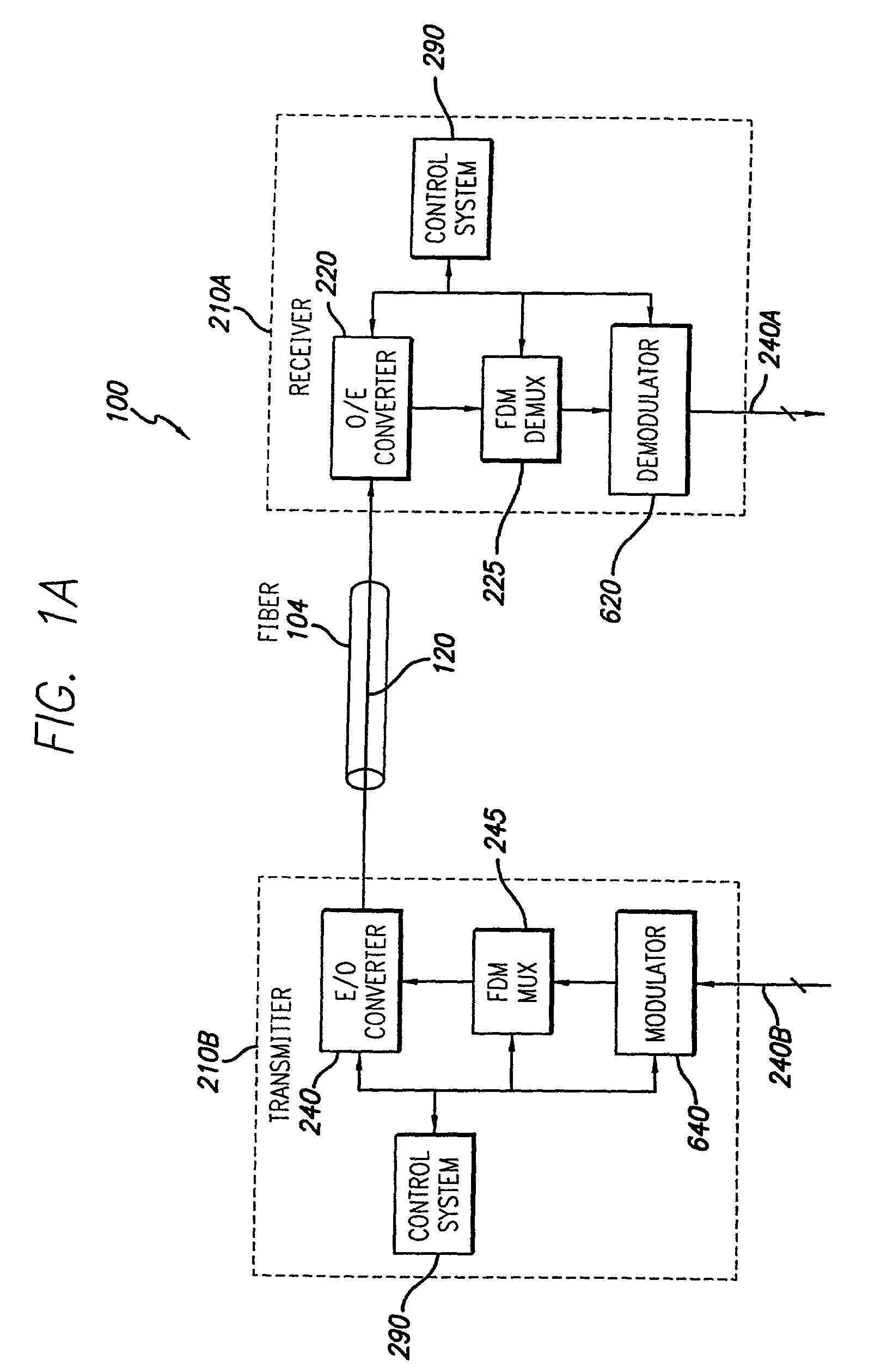
[0038]FIG. 1A is a block diagram of a fiber optic communications system 100 in accordance with the present invention. System 100 includes a transmitter 210B coupled to a receiver 210A by an optical fiber 104. Transmitter 210B and receiver 210A are both based on frequency division multiplexing (FDM). Transmitter 210B includes a modulator 640, FDM multiplexer 245 and E / O converter 240, coupled in series. The modulator 640 applies a modulation to a plurality of incoming signals 240B. The FDM multiplexer 245 combines the modulated signals into a single signal using FDM techniques. E / O converter 240 converts this single signal from electrical to optical form 120. The E / O converter 240 preferably includes an optical source, such as a laser, and an optical modulator, such as a Mach Zender modulator, which modulates the optical carrier produced by the optical source with an incoming electrical signal.

[0039]For convenience, the incoming signals 240B shall be referred to as low-speed data cha...


PUM


Abstract

Data is transmitted across an optical fiber communications system by splitting an incoming tributary into multiple low-speed data channels, modulating each of these into a stream of symbols (e.g., by using QAM modulation) and then frequency division multiplexing a number of symbol streams into a single high-speed channel to be transmitted across a fiber. The receiver reverses this process. In order to preserve the jitter tolerance for the overal system, reference clocks are used to remove unwanted jitter in the timing of the system.

Description

CROSS-REFERENCE TO RELATED APPLICATIONS[0001]This application is a continuation-in-part of U.S. patent application Ser. No. 09 / 571,349, filed May 16, 2000, now abandoned, which is a continuation-in-part of U.S. patent application Ser. No. 09 / 405,367, filed Sep. 24, 1999, now U.S. Pat. No. 6,529,303; which is a continuation-in-part of U.S. patent application Ser. No. 09 / 372,143, filed Aug. 20, 1999, now abandoned; which is a continuation-in-part of U.S. patent application Ser. No. 09 / 229,594, filed Jan. 13, 1999, now U.S. Pat. No. 6,452,594; which is a continuation-in-part of U.S. patent application Ser. No. 09 / 035,630, filed Mar. 5, 1998, now abandoned. The subject matter of all of the foregoing is incorporated herein by reference.BACKGROUND OF THE INVENTION[0002]1. Field of the Invention[0003]This invention relates generally to optical fiber communications systems which use frequency division multiplexing, and more particularly, to maintaining the timing of data transmitted across ...

Claims


Application Information

Patent Timeline
IPC IPC(8): H04J3/06H04J3/02H04J3/04
CPCH04J14/0298H04L1/0057H04L1/0059H04J2203/0089
Inventor PECHNER, DAVID ANEWELL, LAURENCE JKONEZNY, MARK D
Owner FAR NORTH PATENTS LLC
Why Eureka
Try Eureka