Method of determining the capacity of each transmitter antenna in a multiple input/multiple output (MIMO) wireless system

a wireless system and transmitter antenna technology, applied in the field of wireless communication, can solve the problems of difficult to determine the channel qualities of each data stream, and the maximum transmission rate may not optimize the use of individual channels,

Inactive Publication Date: 2006-12-26
LUCENT TECH INC +1
View PDF9 Cites 94 Cited by
  • Summary
  • Abstract
  • Description
  • Claims
  • Application Information

AI Technical Summary

Problems solved by technology

Determining the channel qualities of each data stream is thus very difficult.
Disadvantageously, this single maximum transmission rate may not optimize usage of the individual channels on which the multiple transmitter antennas are transmitting.

Method used


Image

  • Method of determining the capacity of each transmitter antenna in a multiple input/multiple output (MIMO) wireless system
  • Method of determining the capacity of each transmitter antenna in a multiple input/multiple output (MIMO) wireless system
  • Method of determining the capacity of each transmitter antenna in a multiple input/multiple output (MIMO) wireless system

Examples


Embodiment Construction

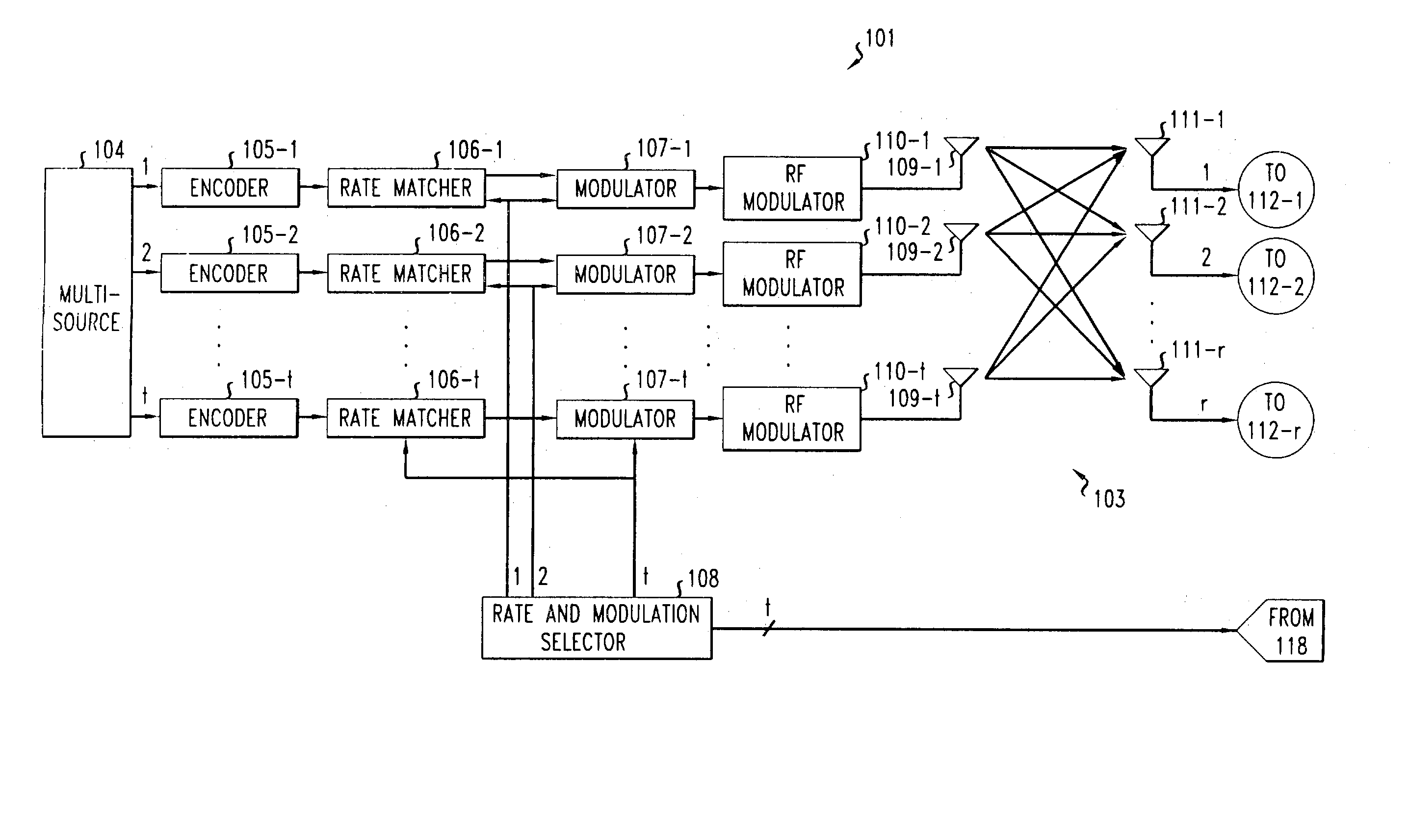
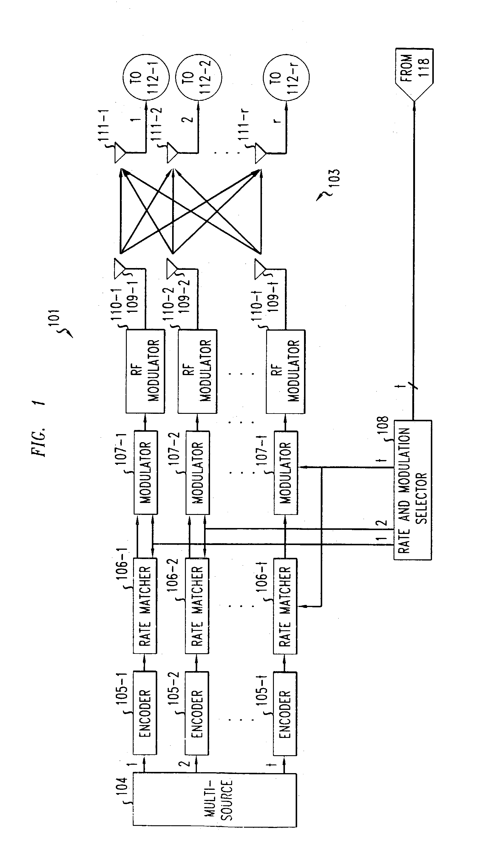
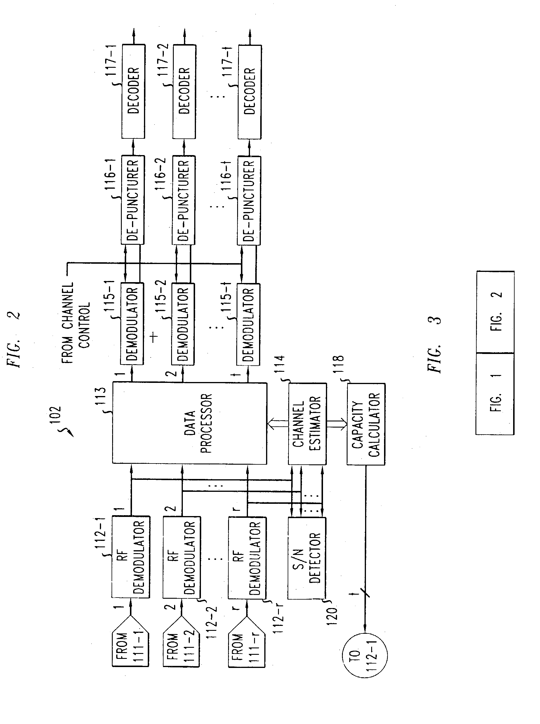
[0009]With reference to FIGS. 1 and 2, a multiple input / multiple output wireless communications system is shown that includes a transmitter end 101 that is communicating with a receiver end 102 over a wireless communication channel 103 via a plurality, t, of simultaneously transmitted data streams. Each of the t data streams transmitted between the transmitter end 102 and the receiver end 103 can be derived from data signals, voice signals, video signals, or any combination of these or other types of digital signals. The communication system can be any type of wireless system employing, for example, well-known time division multiple access (TDMA) techniques, code division multiple access (CDMA) techniques, or any other type of multiple access technique.

[0010]The t data streams that are transmitted over separate channel paths within the communication channel 103 are subject to various impairments that can induce amplitude and phase variations into the received data streams. These imp...


PUM


Abstract

The per antenna capacity of each of the transmitter antennas in a MIMO system are individually determined from measurable information at the receiver end. Specifically, the channel capacity for each individual transmitter antenna is calculated at the receiver end as a function of measurable channel coefficients (also known as channel state information), the measurable average signal-to-noise ratio, and the number of transmitter antennas. Once the per antenna capacity of each transmitter antenna is individually determined at the receiver end, the maximum transmission rate for each data stream transmitted by each transmitter antenna is determined from that individual capacity either at the receiver end and fed back to the transmitter end, or is determined at the transmitter end from the individual transmitter antenna capacities that are fed back by the receiver end to the transmitter end. A modulation scheme that supports each maximum transmission rate is then determined based on some defined criteria.

Description

TECHNICAL FIELD[0001]The invention relates to wireless communication, and more particularly, to Multiple Input / Multiple Output (MIMO) wireless systems.BACKGROUND OF THE INVENTION[0002]The demand for wireless communication for high-speed data communication in addition to voice communication is growing at a fast rate. As this demand continues to grow, systems that are capable of providing both high efficiency and high performance will be increasingly desirable. Multiple Input / Multiple Output (MIMO) systems employ multiple transmitter antennas that transmit to multiple receiver antennas over a wireless channel. Since multiple independent data streams are simultaneously transmitted using the same frequency band, MIMO systems are spectrally highly efficient and, as a result, a higher data throughput is achievable as compared to a single antenna system.[0003]As in all wireless system, the propagation channel is subject to various time-variant channel conditions, or qualities, that cause t...

Claims


Application Information

Patent Timeline
Patent Type & Authority Patents(United States)
IPC IPC(8): H04B7/02H04B17/02H04L1/02H04L27/20H04L7/00H04B7/04H04B7/06H04B17/40H04L1/00H04L1/08
CPCH04B7/04H04L1/0003H04L1/0013H04L1/0068H04B7/061H04B7/0619H04L1/08
Inventor LIU, JUNG-TAORUDRAPATNA, ASHOK N.
Owner LUCENT TECH INC
Why Eureka
Try Eureka