
Apparatus and methods for converting a cryogenic fluid into gas

a technology of apparatus and cryogenic fluid, applied in the field of cryogenic fluid, can solve the problems of gas burning, clogging up the evaporator, and not always being able to transport by pipeline,

Inactive Publication Date: 2007-01-02
MUSTANG ENG
View PDF8 Cites 30 Cited by
  • Summary
  • Abstract
  • Description
  • Claims
  • Application Information

AI Technical Summary

Benefits of technology

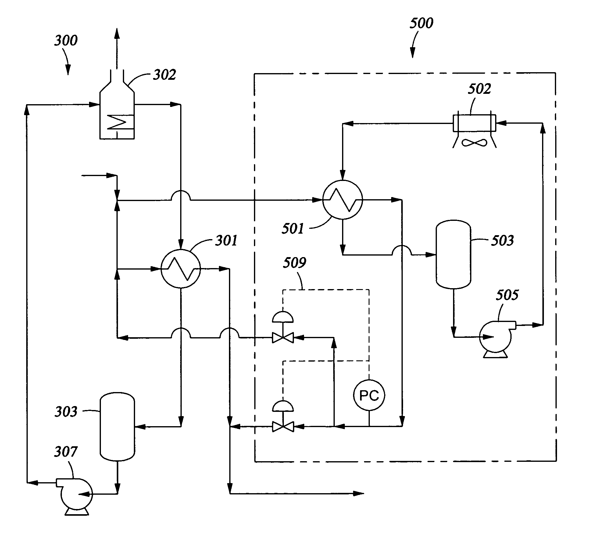
"The present invention provides improved apparatus and methods for processing, transporting, and / or storing LNG. Specifically, the invention provides a method of vaporizing a cryogenic fluid by using heat from ambient air to a heat transfer fluid across a heat transfer surface, which is then transferred to the cryogenic fluid to vaporize it. The invention also provides an apparatus for vaporizing a cryogenic fluid, which includes a heat transfer fluid closed circulation loop and an LNG flow path. Additionally, the invention provides a modified system for vaporizing a cryogenic fluid by adding an ambient air heat exchanger after the heat transfer fluid heater and vaporizer have been in operation in the system. These technical effects improve the efficiency and reliability of LNG processing and transportation."

Problems solved by technology

However, given certain barriers of geography, economics, and / or politics, transportation by pipeline is not always possible, economic or permitted.
Without an effective way to transport the natural gas to a location where there is a commercial demand, the gas may be burned as it is produced, which is wasteful.
Unfortunately, such hot water or steam often freezes so as to give rise to the hazard of clogging up the evaporator.
They do not block up from freezing water, are easy to operate and maintain, but they are expensive to build.
Their use in the USA and Europe is limited and economically difficult to justify for several reasons.
First the present permitting environment does not allow returning the seawater to the sea at a very cold temperature because of environmental concerns for marine life.
Also coastal waters like those of the southern USA are often not clean and contain a lot of suspended solids, which could require filtration.
With these restraints the use of open rack type vaporizers in the USA is environmentally and economically not feasible.
Evaporators of this type are less expensive to build than those of the open rack-type but require heating means, such as a burner, for the preparation of hot water or steam and are therefore costly to operate due to fuel consumption.
Like the intermediate fluid type, the evaporators of the submerged combustion type involve a fuel cost and are expensive to operate.

Method used


Image

  • Apparatus and methods for converting a cryogenic fluid into gas
  • Apparatus and methods for converting a cryogenic fluid into gas
  • Apparatus and methods for converting a cryogenic fluid into gas

Examples


example 1

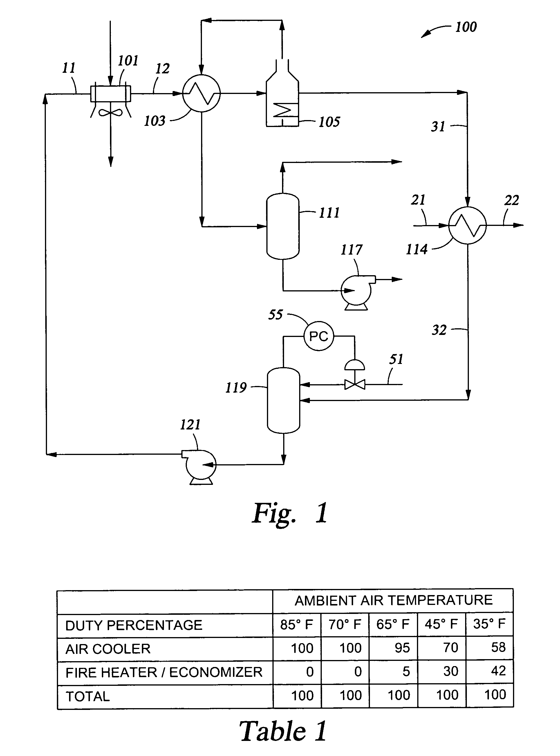
[0060]This example utilizes the apparatus and method as shown in FIG. 1 (11@−10 F, 31@50 F, 32@−10 F, and 119 at 16 psi). The cryogenic fluid is a typical LNG. The circulating fluid utilized is propane. The duty percentage for the air cooler 101, and the combined duty percentage for fired heater 105 and economizer 103 were calculated for ambient air temperatures of 35 F, 45 F, 65 F, 70 F and 85 F, with these percentages presented in the following TABLE 1. The propane circulation is about 1.7 lb propane / lb LNG, with the rate depending upon the temperature and pressure of the LNG and propane. The propane circulation range is estimated to be from about 1.0 to 2.5 lb propane / lb LNG.

[0061]

TABLE 1Duty Percentage at Various Ambient Air Temperatures85 F.70 F.65 F.45 F.35 F.Air Cooler100100957058Fired Heat / Economizer0053042Total100100100100100

example 2

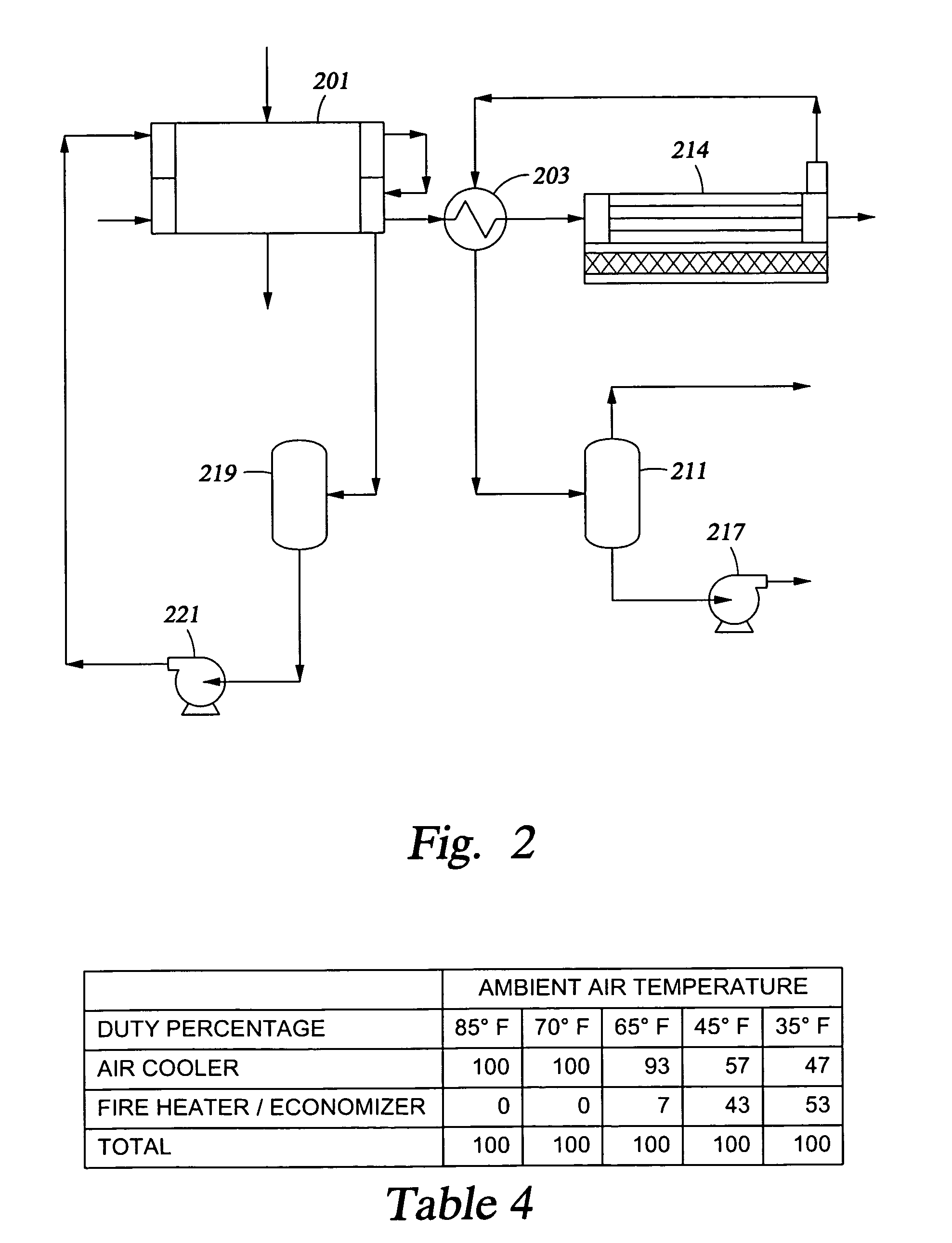
[0062]This example also utilizes the apparatus and method as shown in FIG. 1 (11@−10 F, 31@50 F, 32@−10 F, and 119 at 100 psig). The cryogenic fluid is again a typical LNG. The circulating fluid utilized is propane. The duty percentage for the air cooler 101, and the combined duty percentage for fired heater 105 and economizer 103 were calculated for ambient air temperatures of 35 F, 45 F, 65 F, 70 F and 85 F, with these percentages presented in the following TABLE 2. The propane circulation is about 7.6 lb propane / lb LNG, with the rate depending upon the temperature and pressure of the LNG and propane. The propane circulation range is estimated to be from about 5.0 to 10.0 lb propane / lb LNG.

[0063]

TABLE 2Duty Percentage at Various Ambient Air Temperatures85 F.70 F.65 F.45 F.35 F.Air Cooler100100935747Fired Heat / Economizer0074353Total100100100100100

example 3

[0064]This example again utilizes the apparatus and method as shown in FIG. 1 (11@range of −10 F to 30 F, 30@−10 F, 31@50 F, 32@30 F, and 119 at 16 psig). The cryogenic fluid is a typical LNG. Rather than using propane as the circulating fluid, WBF is utilized. As with Examples 1 and 2, the duty percentage for the air cooler 101, and the combined duty percentage for fired heater 105 and economizer 103 were calculated for ambient air temperatures of 35 F, 45 F, 65 F, 70 F and 85 F, with these percentages presented in the following TABLE 3. The WBF circulation is about 10–30 lb WBF / lb LNG, with the rate depending upon the temperature and pressure of the LNG and propane.

[0065]

TABLE 3Duty Percentage at Various Ambient Air Temperatures85 F.70 F.65 F.45 F.35 F.Air Cooler100100936051Fired Heat / Economizer0074049Total100100100100100


PUM


Abstract

Method and apparatus for vaporizing cryogenic fluids in which an intermediate heat transfer fluid is first heated across a heat transfer surface with ambient air, and then the heat transfer surface provides heat to vaporize the cryogenic fluid.

Description

BACKGROUND OF THE INVENTION[0001]1. Field of the Invention[0002]The present invention relates to cryogenic fluids. In another aspect, the present invention relates to apparatus and methods for processing, transporting and / or storing cryogenic fluids. In even another aspect, the present invention relates to apparatus and methods for converting a cryogenic fluid into a gas. In even another aspect, the present invention relates to methods and apparatus for processing, transporting and / or storing liquified natural gas (“LNG”). In still another aspect, the present invention relates to apparatus and methods for modifying and / or retrofitting cryogenic vaporization systems.[0003]2. Description of the Related Art[0004]Most conveniently, natural gas is transported via pipeline from the location where it is produced to the location where it is consumed. However, given certain barriers of geography, economics, and / or politics, transportation by pipeline is not always possible, economic or permi...

Claims


Application Information

Patent Timeline
Patent Type & Authority Patents(United States)
IPC IPC(8): F17C9/02F17C5/06F17C6/00F17C9/04
CPCF17C5/06F17C9/02F17C9/04F17C6/00F17C2227/0313F17C2221/033F17C2223/0161F17C2223/033F17C2223/046F17C2225/0123F17C2225/033F17C2225/035F17C2227/0135F17C2227/0323F17C2227/0327F17C2227/0332F17C2227/0388F17C2227/0393F17C2265/05F17C2270/0136Y02E60/321Y02E60/32
Inventor BAUDAT, NED P.
Owner MUSTANG ENG
Learn More