Solar collector mounting array

a technology for solar collectors and mounting arrays, which is applied in the direction of solar heat collectors, solar heat collector safety, heat collector mounting/support, etc., can solve the problems of reducing the likelihood of the base assembly moving or otherwise shifting on the roof, unable to re-roof or resurface, and exposing the roof to damag

Inactive Publication Date: 2007-01-02
CYRIUM SOLAR
View PDF30 Cites 67 Cited by
  • Summary
  • Abstract
  • Description
  • Claims
  • Application Information

AI Technical Summary

Benefits of technology

[0005]The solar collector devices may include a directable array or tracking array of optical elements, or a continuous surface typically concentrating sunlight on a receiver may be a photovoltaic cell and the one or more reflectors include an array of mirrors. The concentrator, including the receiver and mirrors, may include a heliostat array. The heliostat array includes: (a) a positioning plate adapted to simultaneously aim each of the plurality of mirrors—each of which is adapted to rotate about a first center of rotation—in a direction bisecting the interior angle between the source and the receiver; and (2) a plurality of reflector positioning arms for operably coupling the plurality of reflectors to the positioning plate, each of the positioning arms being adapted to rotate relative to the positioning plate about a second center of rotation.
[0006]The mast of a directable or tracking array and the footings of a heliostat array for example may engage the system of solar collector support structures to exploit the friction between the system's surface contact pads and a rooftop, thereby enabling the solar collecting device to reside on the rooftop without using fasteners or anchors that might otherwise penetrate the mounting surface and, in this example, expose the roof to damage.

Problems solved by technology

As such, a solar collector is subjected to wind forces they may be large enough to cause the solar collector to move with such motion disrupting the operation of the device.
In addition, depending on the roof-penetrating mounting anchors used, it may be difficult, if not impossible to re-roof or resurface the rooftop with the solar collector support structure anchors present.
The mast of a directable or tracking array and the footings of a heliostat array for example may engage the system of solar collector support structures to exploit the friction between the system's surface contact pads and a rooftop, thereby enabling the solar collecting device to reside on the rooftop without using fasteners or anchors that might otherwise penetrate the mounting surface and, in this example, expose the roof to damage.
This allows the array of base assemblies to be held in compression, and therefore stabilizes the array of base assemblies and reduces the likelihood of the base assemblies moving or otherwise shifting on the roof.
Additionally, the optical elements 132 are deployed in a relatively flattened array, thereby providing a significantly lower wind profile, and thereby significantly lower wind resistance, as compared to a conventional reflective dish.

Method used


Image

  • Solar collector mounting array
  • Solar collector mounting array
  • Solar collector mounting array

Examples


first embodiment

[0057]In some preferred embodiments, the frame of the solar energy concentrator is made to frictionally adhere to a roof using a plurality of footings that distribute the weight of the concentrator and increase the friction inhibiting the concentrator from sliding across the roof under the force of gravity or wind loading or combinations thereof. As illustrated in FIGS. 21A–21C, the heliostat chassis includes a plurality of frame support feet 308, each foot 308 being detachably affixed to a footing that directly engages the roof. In the footing, the footing includes a hollow container 1100 adapted to receive ballast and means to detachably engage the container 1100 to the leg 308. The hollow footing includes a bayonet fitting or threaded mouth 1104 and cap 1105, for example, adapted to receive ballast 1120—preferably water, sand, or gravel—retained within a reservoir therein. As illustrated in the cross section of the hollow footing in FIG. 21 C, the means to detachably engage the l...

second embodiment

[0059]As illustrated in FIGS. 22A and 22B, a concentrator footing includes a subassembly as a means to detachably engage the leg 308 and solid ballast. The exemplary subassembly includes a post 1204 that slidably engages the leg and a bottom plate 1208 for bearing the weight of the sold ballast 1202. As described above, the post detachably engages heliostat leg 308 by means of pins 1206A, 1206B outwardly biased by a spring 1206C. The ballast may be concrete although various other materials, preferably durable and having a relatively high density may also be employed.

third embodiment

[0060]Illustrated in FIGS. 23A and 23B is a concentrator footing. Each of the one or more footings 1300 is a receptacle including a cavity adapted to receive ballast such as an 8 inch cinder block 1310, for example. The footings 1300 are attached to the concentrator by means of fasteners, e.g., bolts, that engage the mounting plate 1308 Movement of the concentrator is inhibited by the cinder block which enhanced the weight and static friction of the via the inner wall 1304 and bottom plate 1306 made of rigid material. Preferably, the outer wall 1302 is inclined to mitigate the force of wind or to induce downward pressure on the footings for purposes of increasing static friction with the underlying roof.

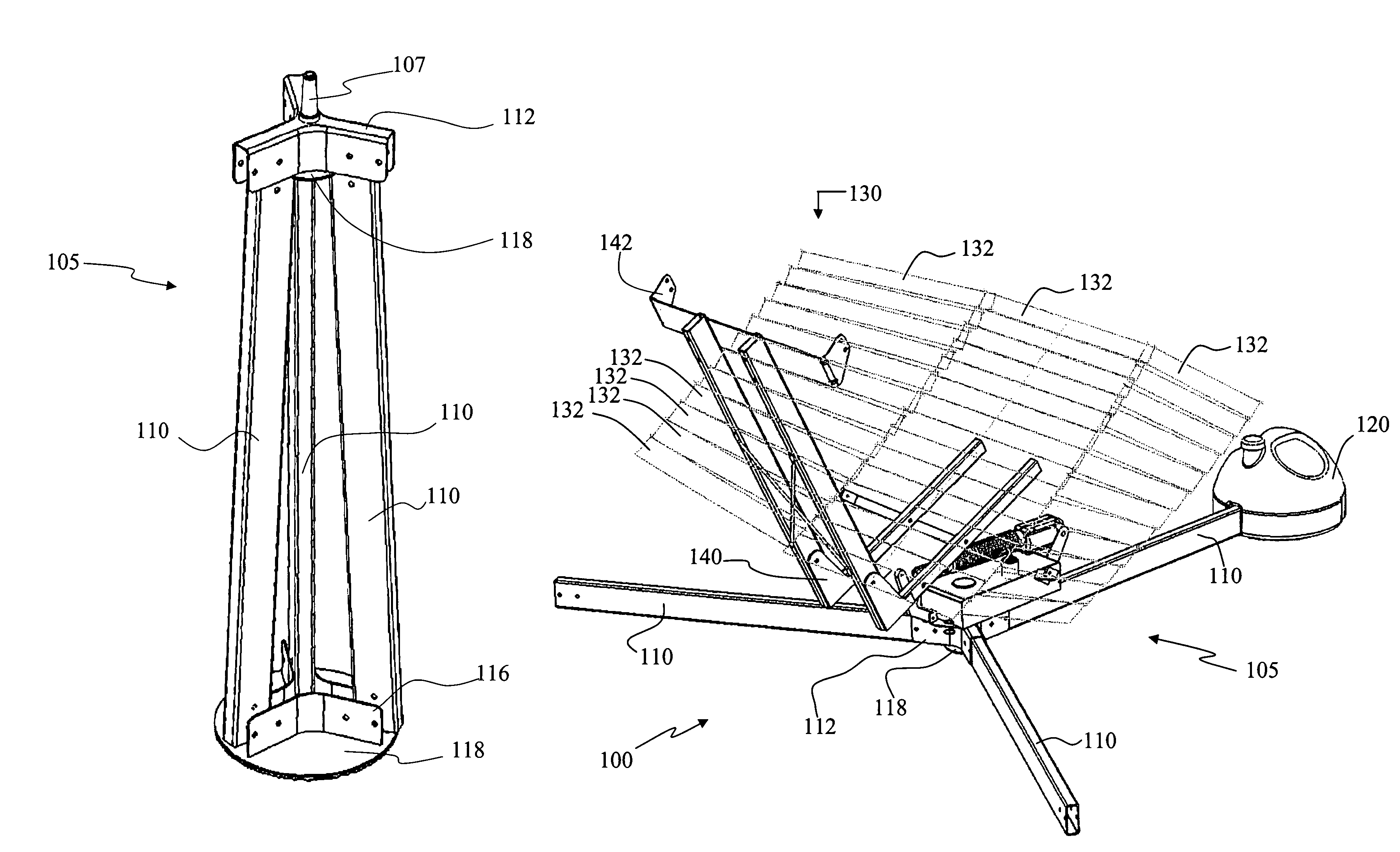
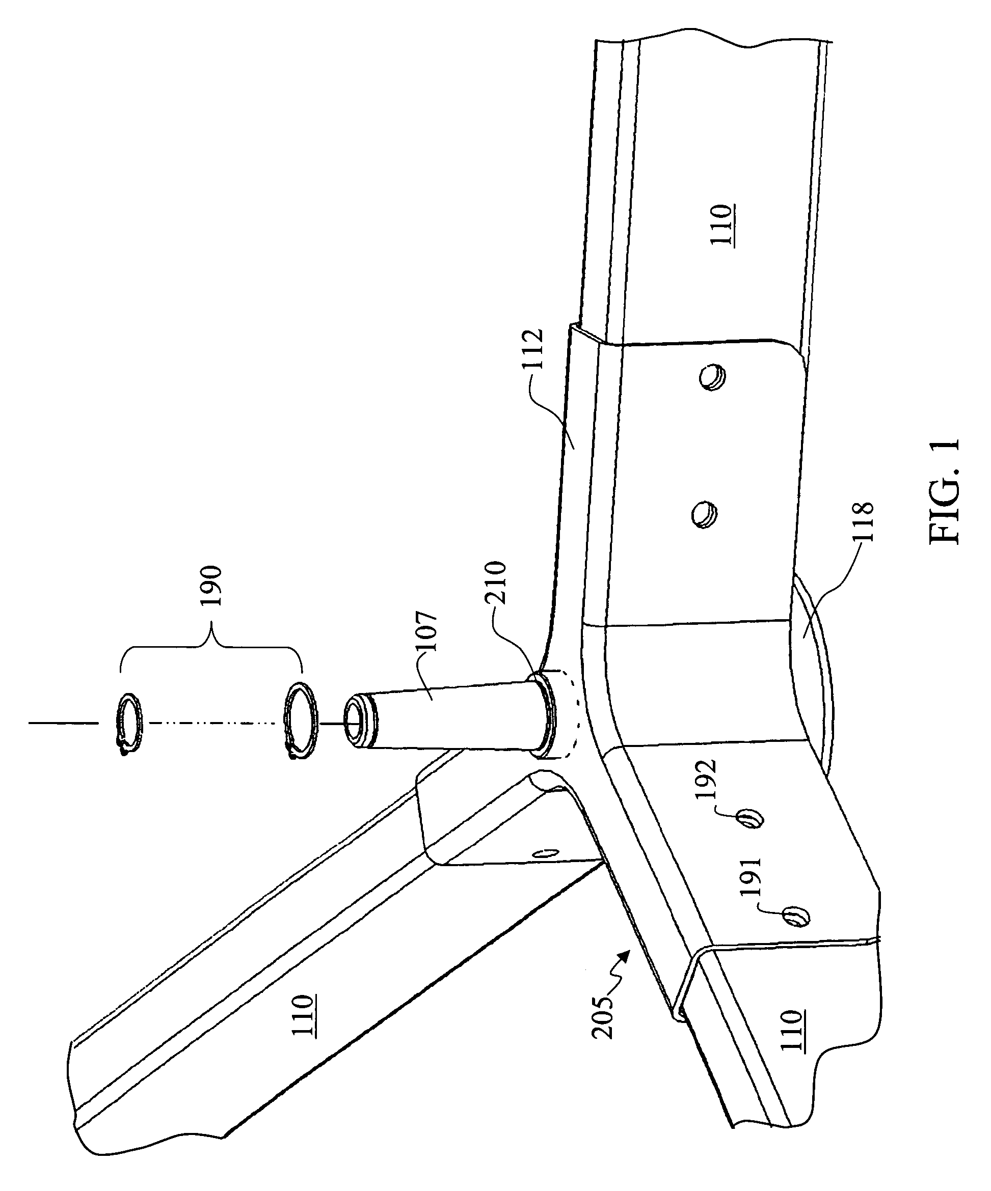
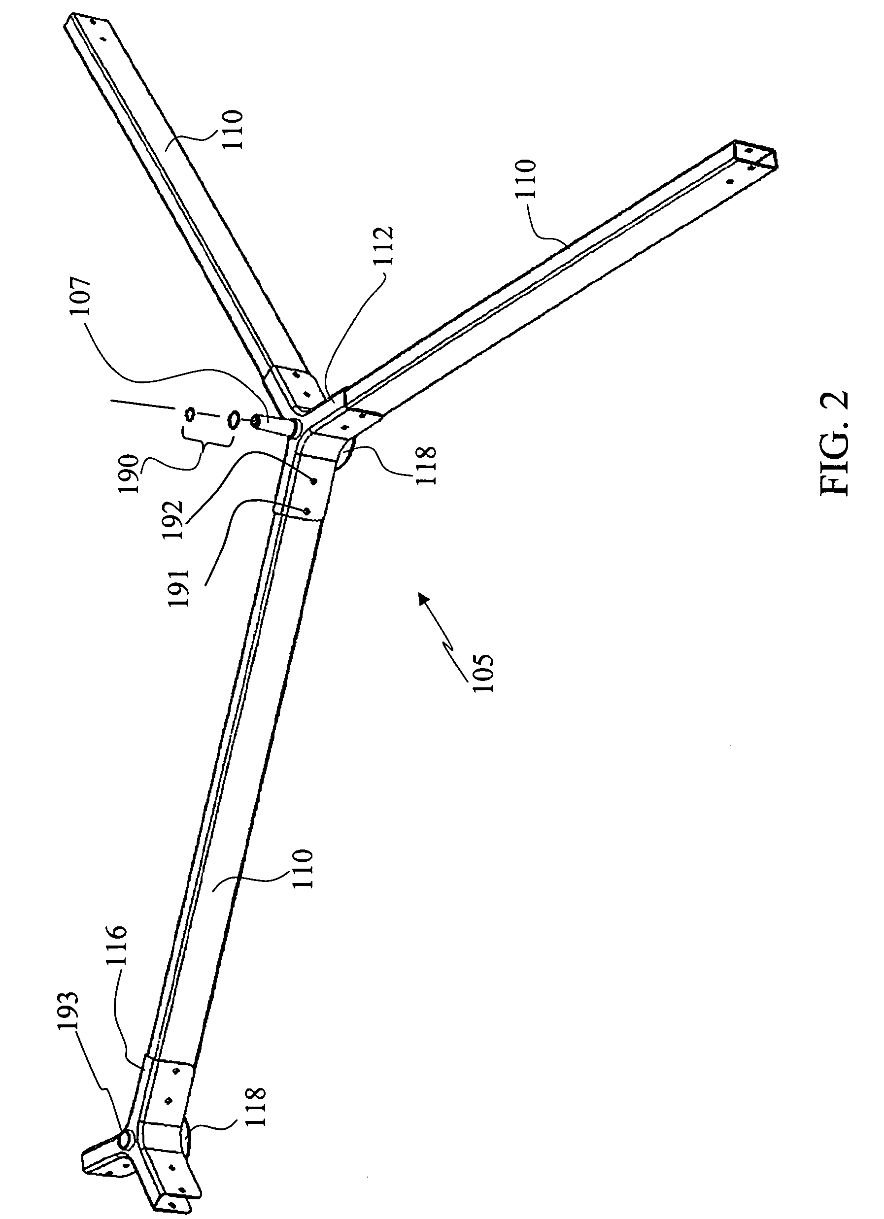
[0061]In addition, the several embodiments of the system of solar collector support structures may be used to secure the heliostat to a mounting surface. For example, junction elements having three or four arms or leg receivers may form three-leg or four-leg base assemblies respectiv...


PUM


Abstract

A solar collector structural support system that affixes to a mounting surface without penetrating the mounting surface is disclosed. The invention in the preferred embodiment includes a junction element adapted to receive: a plurality of leg members; at least one footing adapted to engage frictionally a mounting surface; and a structural support member; wherein a first junction element of the plurality of junction elements receives: a proximal end of a first leg member and a first structural support member. In addition, the junction element may be adapted to receive a ballast element and the ballast element may be adapted to engage a leg member.

Description

CROSS-REFERENCE TO RELATED APPLICATION[0001]This application claims the benefit of U.S. Provisional Patent Application Ser. No. 60 / 576,770 filed Jun. 2, 2004, entitled “ROOFTOP CONCENTRATOR,” which is hereby incorporated herein for all purposes and this application is a continuation-in-part of Non-provisional patent application Ser. No. 11 / 042,031 filed Jan. 24, 2005 entitled “SELF-BALASTING SOLAR COLLECTOR” which claims the benefit of U.S. Provisional Patent Application Ser. No. 60 / 612,592 filed Sep. 22, 2004, entitled “APPARATUS FOR REDIRECTING PARALLEL RAYS USING SIMPLE RIGID TRANSLATION,” of U.S. Non-provisional patent application Ser. No. 11 / 058,023 filed Feb. 14, 2005, entitled “APPARATUS FOR REDIRECTING PARALLEL RAYS USING RIGID TRANSLATION,” and of U.S. Provisional Patent Application Ser. No. 60 / 557,738 filed Mar. 30, 2004, entitled NON-PENETRATING ROOF-MOUNTED TRACKING SOLAR COLLECTOR,” both of which are hereby incorporated by reference herein for all purposes.FIELD OF INVE...

Claims


Application Information

Patent Timeline
Patent Type & Authority Patents(United States)
IPC IPC(8): F24J2/52F24J2/46F24J2/54
CPCF24J2/16H01L31/0547F24J2/5203F24J2/5228F24J2/525F24J2/5256F24J2/526F24J2/5406F24J2/542F24J2/5431F24J2/523F24J2/5233F24J2002/467F24J2002/5292F24J2002/5441F24J2002/5451F24J2002/5458F24J2002/5465F24J2002/5468Y02B10/20Y02E10/47Y02E10/52F24J2/4638F24S23/77F24S25/10F24S25/13F24S25/30F24S25/40F24S25/617F24S25/634F24S25/65F24S30/422F24S30/452F24S30/48F24S40/85F24S2025/02F24S2025/6007F24S2030/115F24S2030/131F24S2030/133F24S2030/135F24S2030/136
Inventor LUCONI, GREGG FREDERICK
Owner CYRIUM SOLAR
Why Eureka
Try Eureka