Method and an assembly unit for performing assembling operations

a technology of assembly unit and assembly unit, which is applied in the direction of programmed manipulators, instruments, programme control, etc., can solve the problems that neither the component to be assembled (e.g. a vehicle door) nor the part on which the assembly is performed are exposed to scratches and other damage, and achieves low cost, small manoeuvre space, and fast, safe and accurate determination of the position of the target

Pending Publication Date: 2022-01-27
ABB (SCHWEIZ) AG
View PDF5 Cites 1 Cited by
  • Summary
  • Abstract
  • Description
  • Claims
  • Application Information

AI Technical Summary

Benefits of technology

[0020]The use of a location utensil attached to the industrial robot that performs the assembly allows the target position for each particular part to be accurately determined, registered, and used for the assembly operation, thus overcoming the difficulties associated with irregular or imprecise placement of the parts, poor repeatability, etc. and providing precise and safe assembly operations. Furthermore, neither the component to be assembled (e.g. a vehicle door) nor the part on which the assembly is performed are exposed to scratches and other damage that may be caused from unwanted contact of the component itself with the target, as may happen in a conventional assembly operation that is guided by force control, especially in certain operations where there is little space to manoeuvre.
[0021]Furthermore, a dedicated location utensil may allow a fast, safe and accurate determination of the position of the target, because, unlike the component to be assembled, the location utensil may be designed with any shape or configuration that is convenient for facilitating the approach to the target and the contact with it, and for providing a very stable contact with targets of any shape, dimension and orientation. A dedicated utensil may also be designed with surfaces that reduce the risk of damage to the target and provide a smooth contact with the target, e.g. with a coating of polytetrafluoroethylene (PTFE), elastomers or the like.
[0022]On the other hand, compared with vision control, force control may be more robust in certain conditions, and be less affected for example by poor light conditions, colour of the target, etc.

Problems solved by technology

Furthermore, neither the component to be assembled (e.g. a vehicle door) nor the part on which the assembly is performed are exposed to scratches and other damage that may be caused from unwanted contact of the component itself with the target, as may happen in a conventional assembly operation that is guided by force control, especially in certain operations where there is little space to manoeuvre.

Method used


Image

  • Method and an assembly unit for performing assembling operations
  • Method and an assembly unit for performing assembling operations
  • Method and an assembly unit for performing assembling operations

Examples


Embodiment Construction

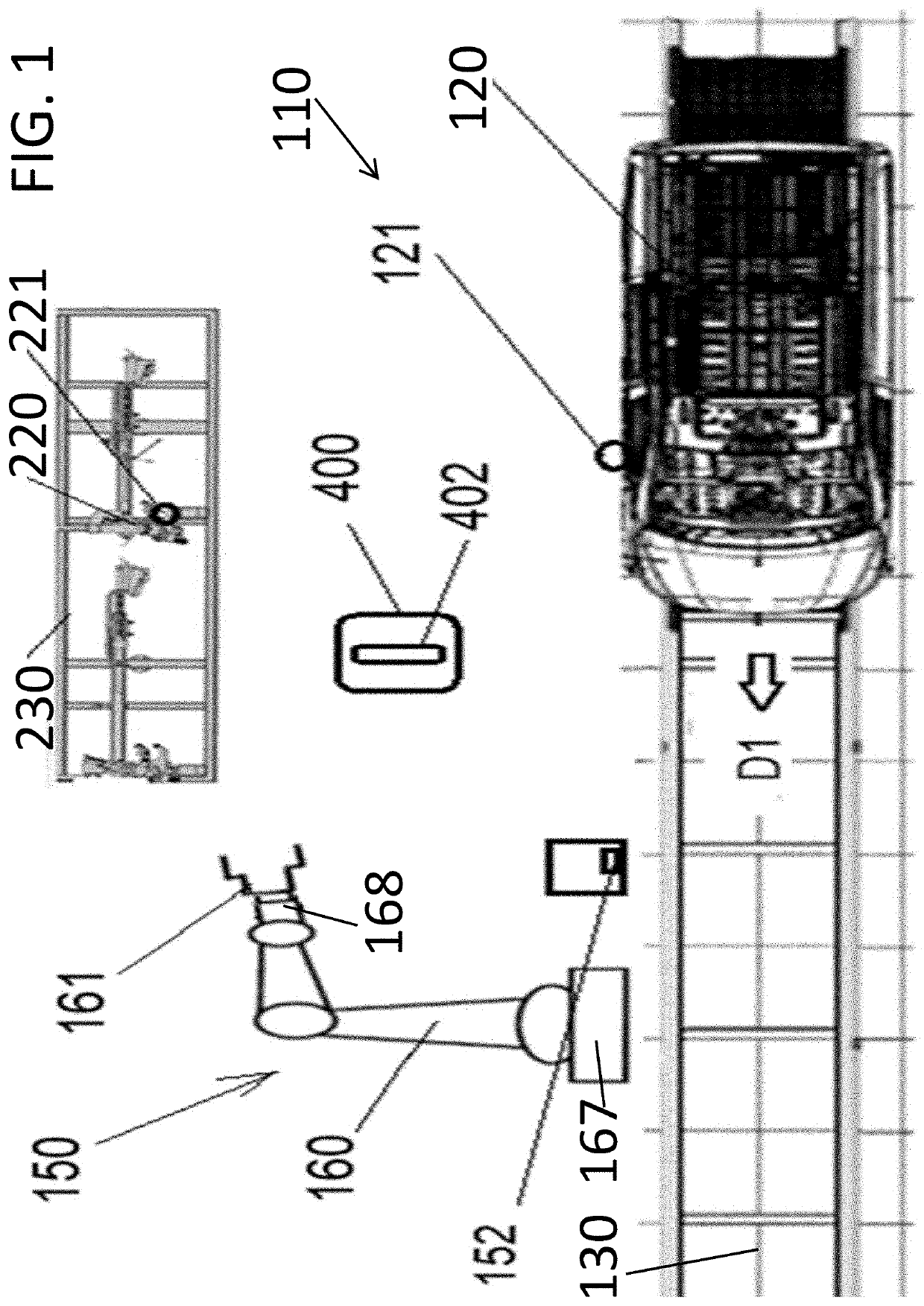
[0077]FIG. 1 shows schematically, and not at scale, an assembly line 110, in the example an automotive final assembly line, where a transporting system 130 advances a part, in the example a vehicle body 120, in an advance direction D1, past an assembly unit or system 150.

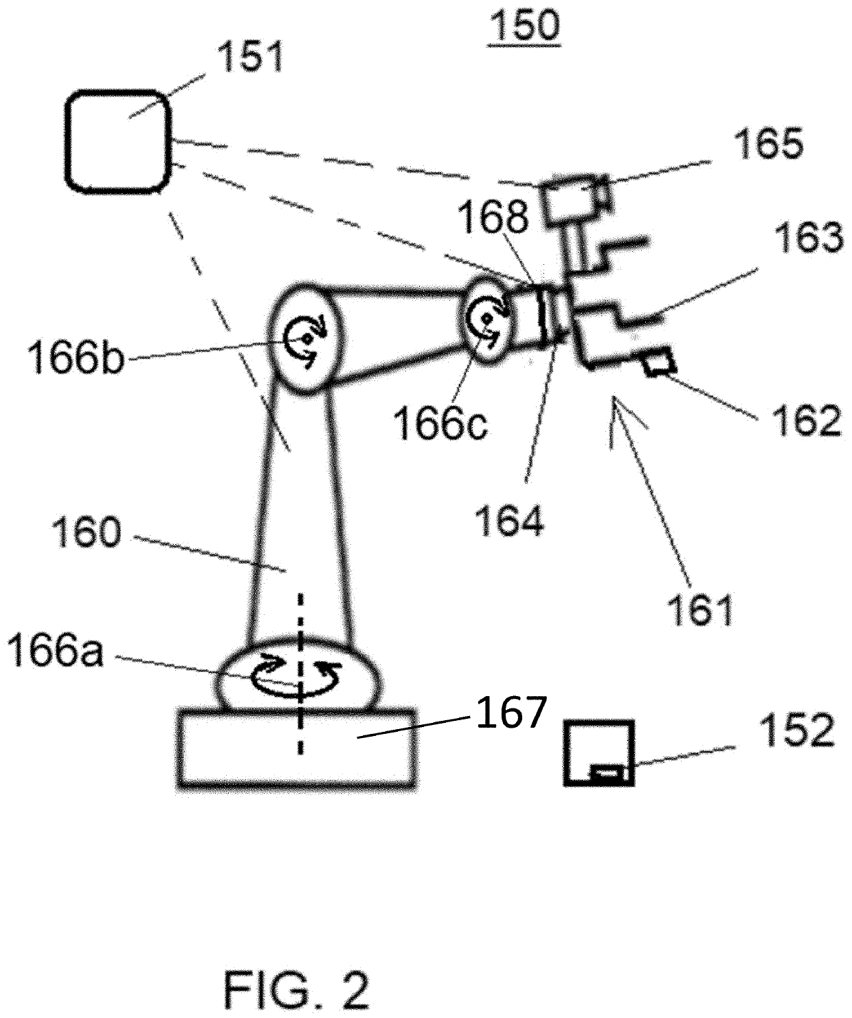
[0078]The assembly unit or system 150 includes an industrial robot 160, which may include a controller and a number of programmable axes (e.g., axes 166a, 166b and / or 166c inter alia, as shown in FIG. 2), i.e. rotational and / or linear degrees of freedom, between a robot base and a robot wrist, each axis having an associated driving element, such as a motor, controlled by the robot controller. The configuration of an industrial robot is known, and the details are not shown in the figures.

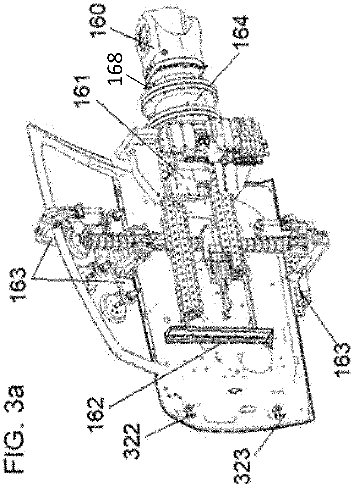
[0079]The robot 160 may be provided with an end effector 161 attached to the robot wrist 168, to perform a certain operation, for example a gripper, a tool, a support for holding a part to be assembled, etc. The robot base 167 may be...


PUM


Abstract

A method is disclosed, including: providing a part having a target at which an assembly operation is to be performed by an industrial robot; determining the target position, by controlling the end effector of the robot to approach the target, detecting a contact between a location utensil attached to the end effector and the target and controlling the end effector of the robot at least by force control until the location utensil reaches a predetermined position relative to the target, and determining the target position as indicated by the absolute position of the location utensil when the location utensil is in said predetermined position relative to the target; registering the target position; and controlling the end effector of the robot to perform the assembly operation at the registered target position. An assembly unit or system is also disclosed.

Description

[0001]The present disclosure is related to a method and to an assembly unit or system for performing an assembling operation on a part having a target for the assembling operation. Also disclosed is an assembly line, for example an automotive final assembly line, with such an assembly unit or system.BACKGROUND[0002]Automotive production lines for manufacturing vehicle bodies usually include a final assembly line where human operators and / or robots may operate to assemble components such as seats, doors, windshields, wheels, steering mechanisms, etc. on vehicle bodies that are advanced along the assembly line by suitable transporter such as chain conveyors, overhead conveyors, AGVs (Automated Guided Vehicles), etc.[0003]An assembly robot for such an assembly line may typically be an industrial robot, provided with an end effector that carries a tool for performing an operation and / or carries a component (e.g. a wheel, a door, etc.) for attaching the component to the vehicle body. The...

Claims


Application Information

Patent Timeline
Patent Type & Authority Applications(United States)
IPC IPC(8): B25J9/16B25J13/08B62D65/06
CPCB25J9/1697B25J9/1633B25J9/1664B62D65/06B25J13/089B25J13/082B25J9/1684B62D65/024B62D65/028B62D65/14B62D65/18G05B2219/36048B25J9/1687G05B19/401
Inventor FREIRE, JESÚSVIDAL RIBAS, JORGERODRÍGUEZ MUÑIO, SERGI
Owner ABB (SCHWEIZ) AG
Why Eureka
Try Eureka