Vertically movable partition walls

a vertical movement, partition wall technology, applied in the field of vertical movement of partition walls, can solve the problems of requiring additional structural support requirements and efficient storage, and achieve the effect of simple and economical construction, constant load on the support structure, and simple structur

Active Publication Date: 2007-01-02
SKYFOLD INC
View PDF11 Cites 16 Cited by
  • Summary
  • Abstract
  • Description
  • Claims
  • Application Information

AI Technical Summary

Benefits of technology

[0008]The partition wall according to the present invention has many advantages. Because its components move vertically rather than horizontally, storage space is not required to the side of the area within which the wall operates, since the wall folds up into and stores in a space above the area in question. Furthermore, because the wall does not move horizontally, the loads imposed on the support structure are constant. As well, it provides a relatively simple and economical construction for a partition wall.

Problems solved by technology

Conventional horizontally movable partition wall systems have problems of efficient storage and require additional structural support requirements.

Method used


Image

  • Vertically movable partition walls
  • Vertically movable partition walls
  • Vertically movable partition walls

Examples


Embodiment Construction

[0016]In the following description, similar features in the drawings have been given similar reference numerals.

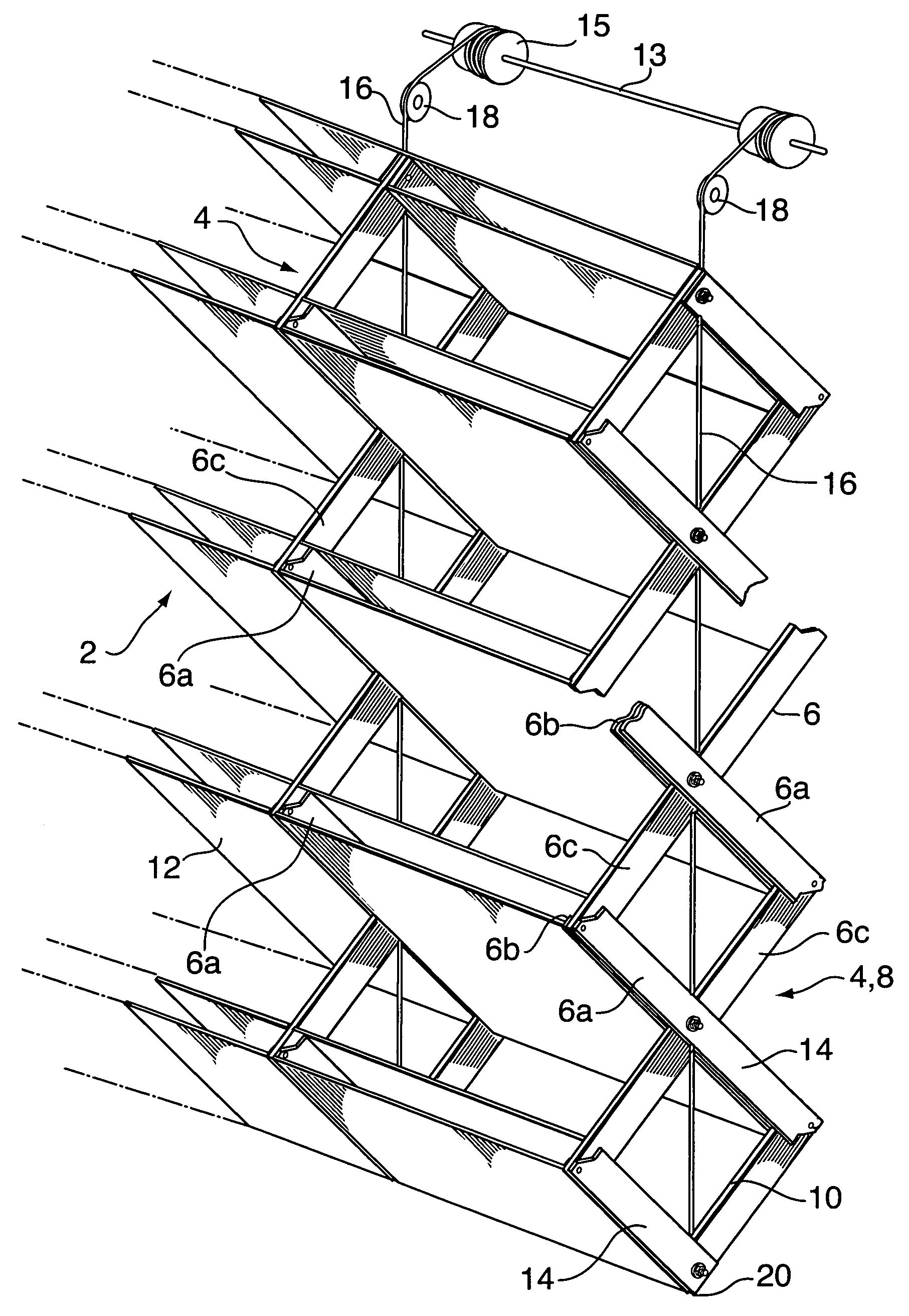
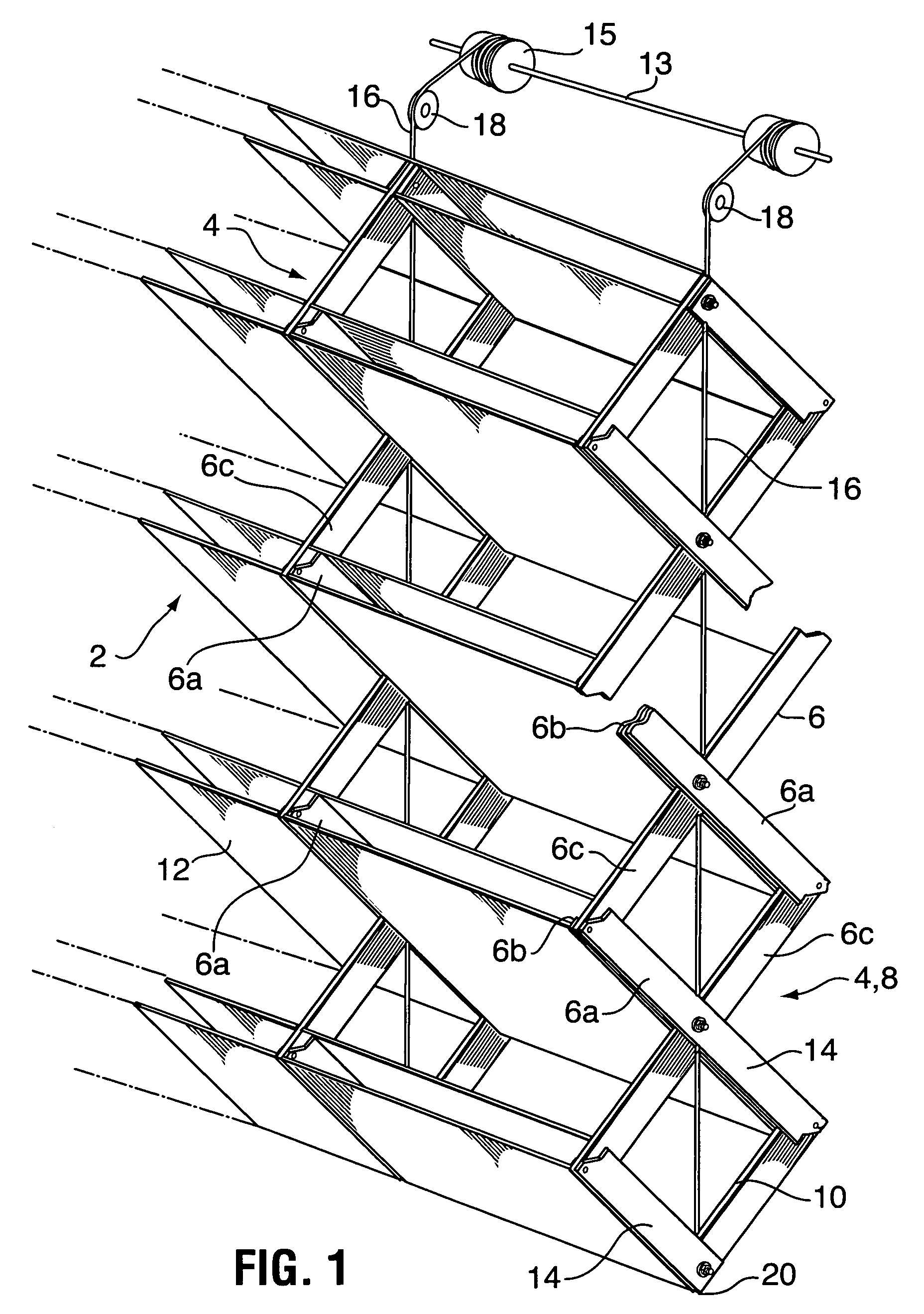
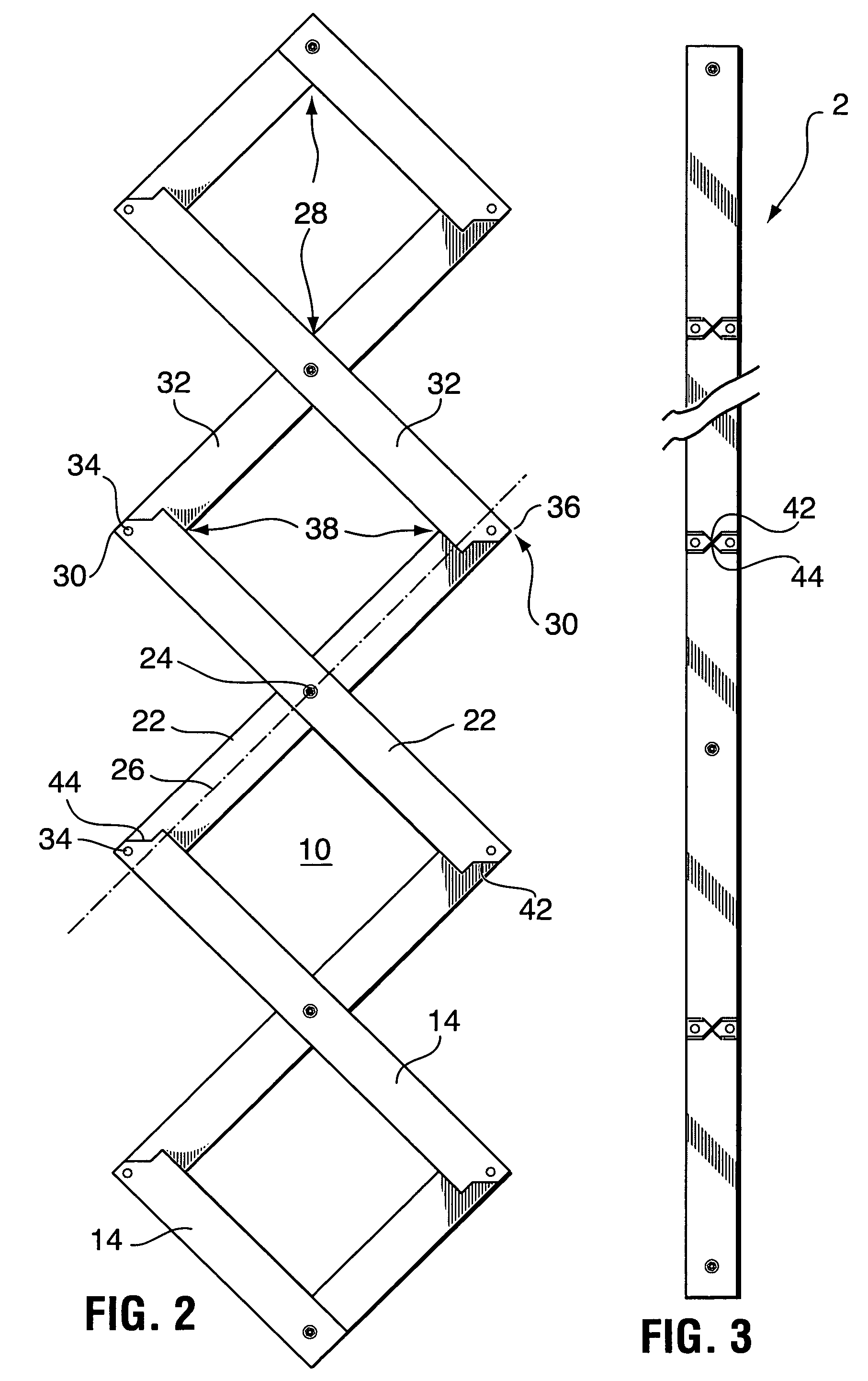
[0017]Turning to FIG. 1, there is illustrated a partition wall 2 in accordance with the present invention in an intermediate position between an upper, storage position and a down position where the wall is in vertical orientation (FIGS. 3 and 5). As can be seen in FIGS. 1 and 2, a plurality of similar trains 4 of elongated members 6 are provided, the members 6 of each train 4 arranged to form a single pantograph 8 forming longitudinally aligned rows of diamonds 10 (FIG. 2). While two trains have been illustrated in FIG. 1, any number of trains may be spaced laterally to form a wall of appropriate width. These trains lie in the vertical plane of the wall and are oriented so that the diamonds 10 of the pantographs lie and operate in a plane at a 90° angle to that wall plane.

[0018]A plurality of panels 12 are provided, secured to members 6 as will be discussed in more detail...


PUM


Abstract

A partition wall, upwardly movable into storage position and downwardly movable into vertical, down position. The wall comprises a plurality of similar trains of elongated members. The members of each train are arranged to form a single pantograph forming longitudinally aligned rows of diamonds. The trains are spaced laterally to form a wall plane and oriented so that the diamonds of the pantographs operate in a plane at a 90° angle to that wall plane. A plurality of panels are provided, each panel being secured to a pair of corresponding members in adjacent trains. The panels are secured to corresponding pairs of opposed sides of the diamonds. Means are provided to raise and lower the trains at a similar rate. The pantographs are contracted when the wall is in a storage position and the elongated when the wall is in down position. The panels form a vertical wall when the pantographs are elongated in down position.

Description

FIELD OF THE INVENTION[0001]The present invention relates to partition walls and more particularly to vertically movable partition wall for use within buildings, for example to cordon off areas, as required, to prevent public access, for crowd control, or for reconfiguring usable space in a building.BACKGROUND OF THE INVENTION[0002]Conventional movable partition wall systems usually take the form of horizontally sliding panels, and are used for example to close or section off areas in buildings. These types of partition wall systems usually require storage space beside the area being closed off, to accommodate the panels when not in use.[0003]U.S. Pat. No. 5,062,464 of Miles Peterson, issued Nov. 5, 1991 describes and illustrates a partition wall which uses a pantograph type of construction to provide a rigid wall section, which is vertically collapsible and movable to a storage position. Conventional horizontally movable partition wall systems have problems of efficient storage and...

Claims


Application Information

Patent Timeline
Patent Type & Authority Patents(United States)
IPC IPC(8): E06B9/06E05F15/00E05F15/10E06B3/92
CPCE06B3/928E05F15/605
Inventor PETERSON, MILES E.
Owner SKYFOLD INC
Why Eureka
Try Eureka