
Solenoid actuated flow controller valve

a flow controller and solenoid technology, applied in the direction of valve operating means/releasing devices, fuel injecting pumps, machines/engines, etc., can solve the problems of reducing the accuracy of affecting the response time of the flow controller valve, and variable amount of overtravel of the armature assembly, so as to reduce the secondary impact and accurate metering and timing of fuel

Active Publication Date: 2007-01-02
CUMMINS INC
View PDF15 Cites 29 Cited by
  • Summary
  • Abstract
  • Description
  • Claims
  • Application Information

AI Technical Summary

Benefits of technology

[0012]One advantage of the present invention is in providing a solenoid actuated flow controller valve that allows accurate metering and timing of the fuel.
[0013]Still another advantage of the present invention is in providing such a solenoid actuated flow controller valve that reduces the secondary impact so as to maintain the sealing margin and / or maximum system operating pressure.
[0014]These and other advantages are provided by a flow control valve for controlling the flow of fuel in a fuel system in accordance with one embodiment of the present invention, the flow control valve comprising a housing including a fuel passage, a valve device movable to close the fuel passage to block fuel flow through the fuel passage, and to open the fuel passage to permit fuel flow through the fuel passage, a valve plunger engaging the valve device, the valve plunger being adapted to reciprocally move between an extended position in which the valve device is moved to the closed position, and a retracted position in which the valve device is moved to the open position, an actuator means for reciprocally moving the valve plunger, the actuator means including a solenoid assembly including a coil capable of being energized to move the valve plunger into the retracted position and an armature connected to the valve plunger for movement with the valve plunger toward the extended position, an armature overtravel means for permitting continued movement of the armature relative to the valve plunger from an engaged position into a disengaged position when the valve plunger reaches the extended position, the armature overtravel means including an overtravel biasing means for returning the armature from the disengaged position to the engaged position prior to subsequent energization of the coil, and an armature stop means for stopping overtravel of the armature.
[0015]In accordance with one implementation, a valve seat is formed on the housing for sealing engagement by the valve device, the overtravel biasing means being positioned axially between the valve seat and the armature. The overtravel biasing means includes an overtravel biasing spring extending around the valve plunger in one embodiment. An armature sleeve may be provided circumscribing around at least a portion of the valve plunger.
[0016]In accordance with one preferred embodiment, the valve device includes a ball valve and a valve guide, as well as a retainer that circumscribes around at least a portion of the valve plunger and abuts the armature. One end of the overtravel biasing spring abuts the retainer while another end of the overtravel biasing spring abuts the valve guide of the valve device. In accordance with an alternative embodiment, the housing of the flow control valve includes a recess cavity for receiving the armature, the recess cavity including an inner bottom surface, the other end of the overtravel biasing spring abutting the inner bottom surface of the recess cavity.
[0017]In accordance with another implementation of the present invention, the armature stop means of the flow control valve includes a fluid film gap that fluidically resists overtravel movement of the armature, resistance to overtravel movement of the armature being determined at least partially by the dimension of the fluid film gap. The fluid film gap may be positioned between the retainer and the valve guide. In another embodiment, the retainer may include an upper piece that abuts the armature, and a lower piece secured to an end of the valve plunger. In such an embodiment, the fluid film gap may be positioned between the upper piece and the lower piece of the retainer, and the overtravel biasing spring also positioned between the upper piece and the lower piece of the retainer.

Problems solved by technology

As previously noted, a limitation in the solenoid actuated flow controller valve of Benson et al. has been found in that there is variation in the amount of overtravel by the armature assembly.
Such variation in the amount of overtravel negatively affects the response time of the flow controller valve and reduces accurate metering and timing of the fuel.
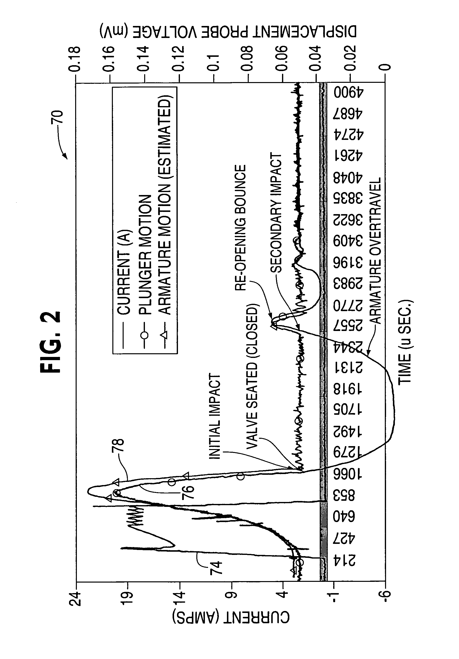
In addition, significant secondary impact has been found to occur as the armature assembly travels in the return direction after overtravel is completed.
During secondary impact of the armature assembly, the load on the seat is reduced, thereby reducing the sealing margin between the valve and the valve seat and consequently, limiting the maximum system operating pressure.
In addition, the secondary impact has also been found to negatively affect fuel metering, and in the worst case scenario, also cause secondary injection.

Method used


Image

  • Solenoid actuated flow controller valve
  • Solenoid actuated flow controller valve
  • Solenoid actuated flow controller valve

Examples


Embodiment Construction

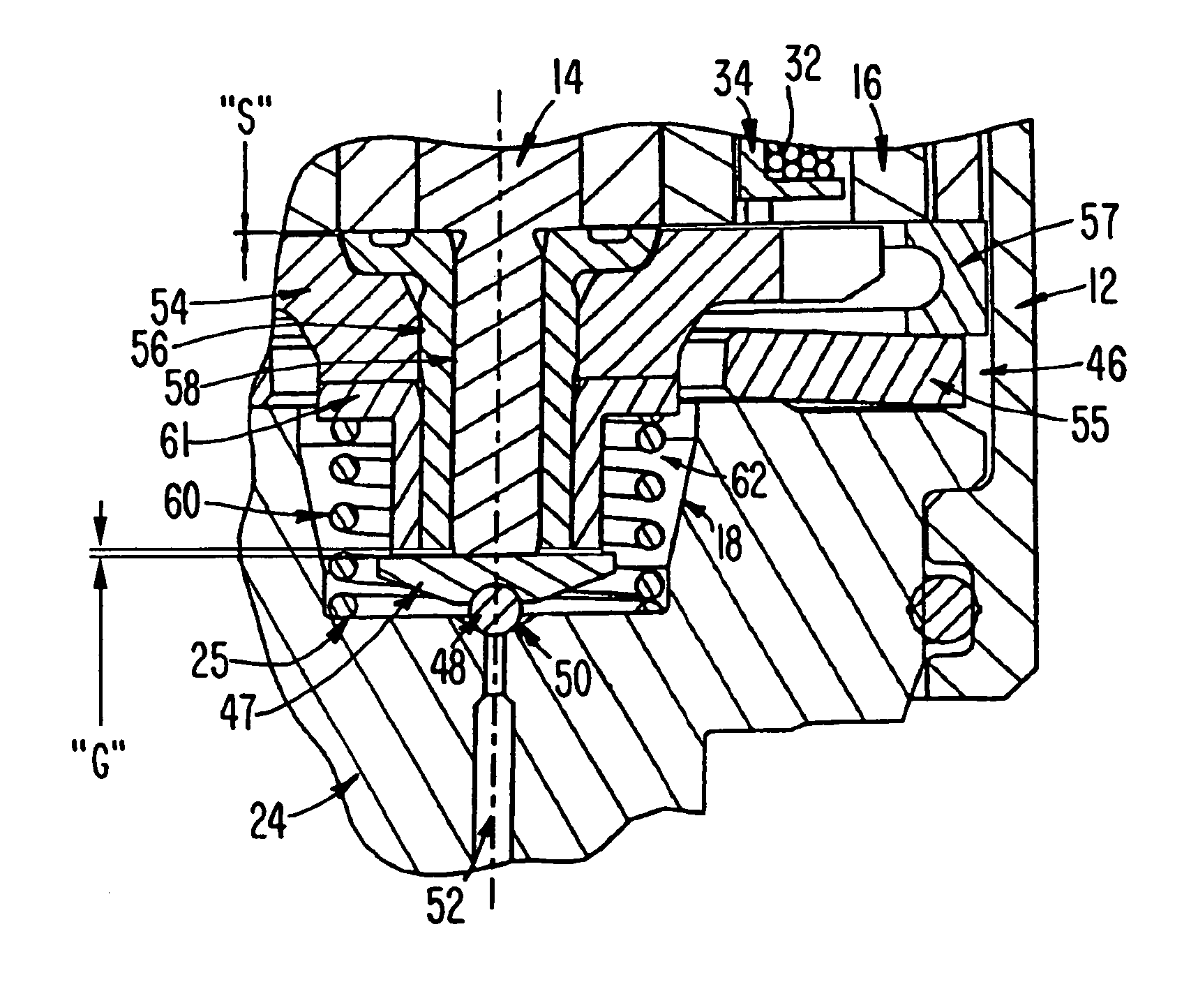
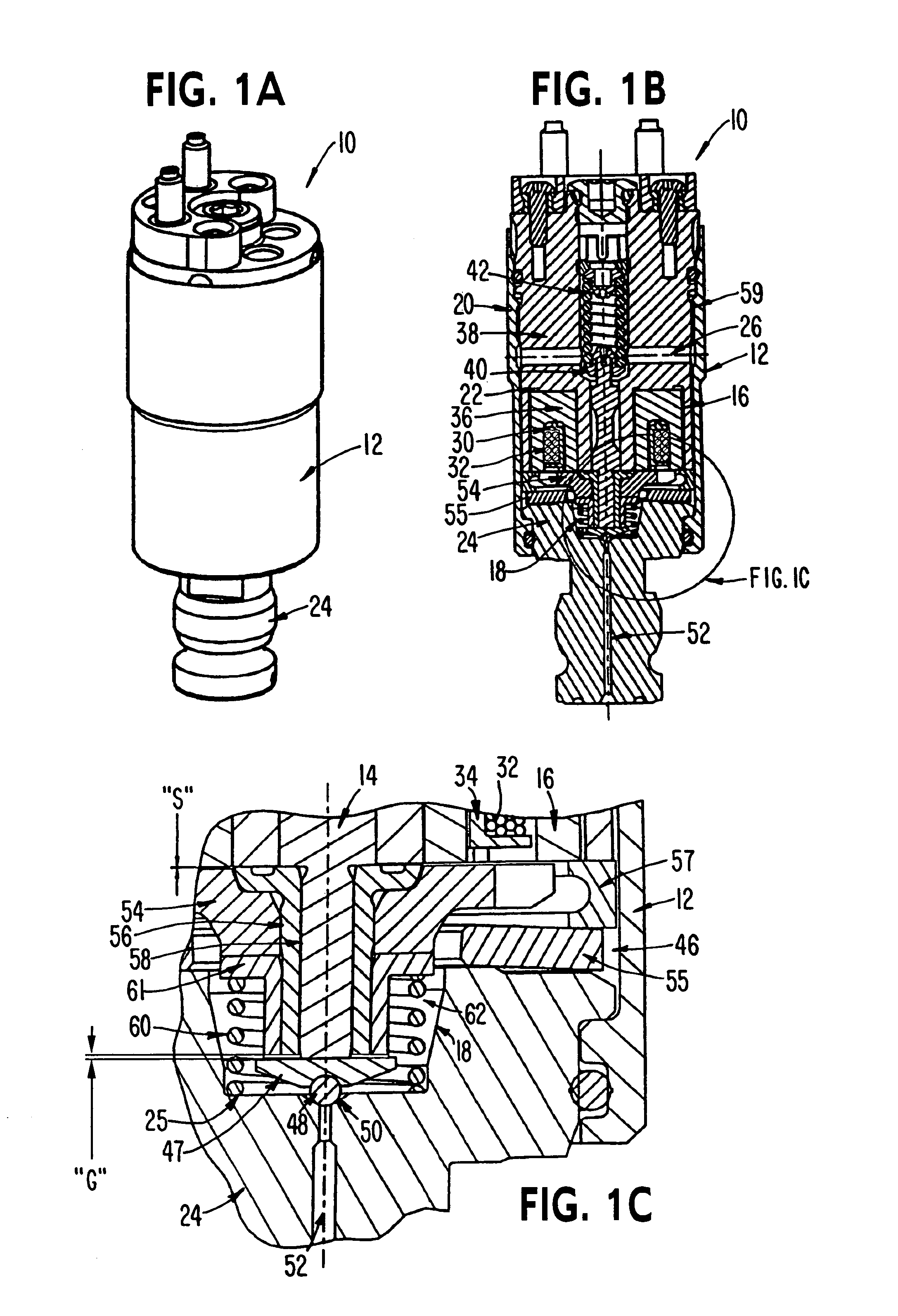
[0033]FIG. 1A illustrates a perspective view of a solenoid actuated flow controller valve 10 in accordance with one example embodiment of the present invention which provides various advantages over flow controller valves of the prior art. As will be explained, the solenoid actuated flow controller valve 10 minimizes variation in the amount of overtravel by the armature. This increases accuracy in metering and timing of fuel provided through the flow controller valve 10, for example, the flow of fuel through a fuel injection system in an internal combustion engine. Furthermore, as also described below, the flow controller valve 10 reduces the secondary impact caused by the returning armature as compared to prior art flow controller valves. This allows the sealing margin to be maintained so that maximum system operating pressure is not reduced.

[0034]Solenoid actuated flow controller valve 10 is provided with armature overtravel feature such as that generally disclosed in U.S. Pat. No...


PUM


Abstract

A flow control valve for controlling the flow of fuel in a fuel system including a housing with a fuel passage, a valve device movable to close the fuel passage to block fuel flow through the fuel passage, and to open the fuel passage to permit fuel flow through the fuel passage, a valve plunger engaging the valve device, an actuator for reciprocally moving the valve plunger, an armature overtravel feature for permitting continued movement of the armature relative to the valve plunger from an engaged position into a disengaged position when the valve plunger reaches the extended position, and an armature stop for stopping overtravel of the armature.

Description

BACKGROUND OF THE INVENTION[0001]1. Field of the Invention[0002]The present invention is directed to a solenoid actuated flow control controller valve for a fuel system. In particular, the present invention is directed such a flow control controller valve with armature overtravel.[0003]2. Description of Related Art[0004]Electromagnetically actuated control valves are widely used in fuel injectors and timing fluid / injection fuel metering systems for precisely controlling the timing and metering of the injected fuel as well as timing fluid. Precise control of the timing and metering of fuel as well as timing fluid is necessary to achieve maximum efficiency of the fuel system of an internal combustion engine. This requires valve designers to consider these performance requirements in their designs. In addition, valve designers continually attempt to reduce the size of the control valves to reduce the overall size and weight of the engine and permit the control valves to be easily mount...

Claims


Application Information

Patent Timeline
Patent Type & Authority Patents(United States)
IPC IPC(8): F02M47/02B05B1/30F02M51/06F02M59/00F02M59/46F02M63/00F02M69/54
CPCF02M47/027F02M63/0015F02M63/0071F02M63/0075F02M63/0078F02M63/007F02M51/0646F02M51/066F02M63/004F02M63/0043F02M2200/306F02M69/54F02M2200/304F02M63/0022
Inventor LUCAS, MICHAEL A.BUCHANAN, DAVID L.RIX, DAVID M.MORRIS, JR., C. EDWARDBENSON, DONALD J.
Owner CUMMINS INC
Learn More