Water aeration device and method

a technology of water aeration and water body, which is applied in the direction of liquid degasification, separation processes, transportation and packaging, etc., can solve the problems of inefficiency of systems, failure to meet the needs of life in such bodies of water, and depletion of oxygen and other elements required to sustain life therein

Inactive Publication Date: 2007-01-02
CHAPMAN TEDDIE C +1
View PDF21 Cites 23 Cited by
  • Summary
  • Abstract
  • Description
  • Claims
  • Application Information

AI Technical Summary

Benefits of technology

[0023]It is a still further object of the present invention to provide an apparatus and method capable of producing an air / water ratio of up to 10 to 1.

Problems solved by technology

Bodies of water, such as lakes, ponds, canals, pools, and the like suffer from the growth of algae and other undesirable aquatic biota that lead to the depletion of oxygen and other elements required to sustain life therein.
Smaller bodies of water in stagnant areas often do not have this resource and as a result, the life forms living in such bodies of water often succumb to the absence of oxygen or relocate to other more oxygenated areas.
As discussed more fully below, such systems are inefficient and subject to malfunction
This system does not create sufficient suction to saturate the water with air due to the tapered nature of the entrance to the exit cylinder.
A further drawback occurs in that cavitation does not occur in the exit cylinder.
While this system is capable of partial aeration, it cannot attain oxygen levels sufficient to provide the desired results in a lake, pond, canal, pool or the like.
All of the aforementioned aeration systems suffer from certain shortcomings, some more serious than others.
Any of the deficiencies suffered by these devices can result in losses in efficiency and ultimately result in economic losses.

Method used


Image

  • Water aeration device and method
  • Water aeration device and method
  • Water aeration device and method

Examples


example 1

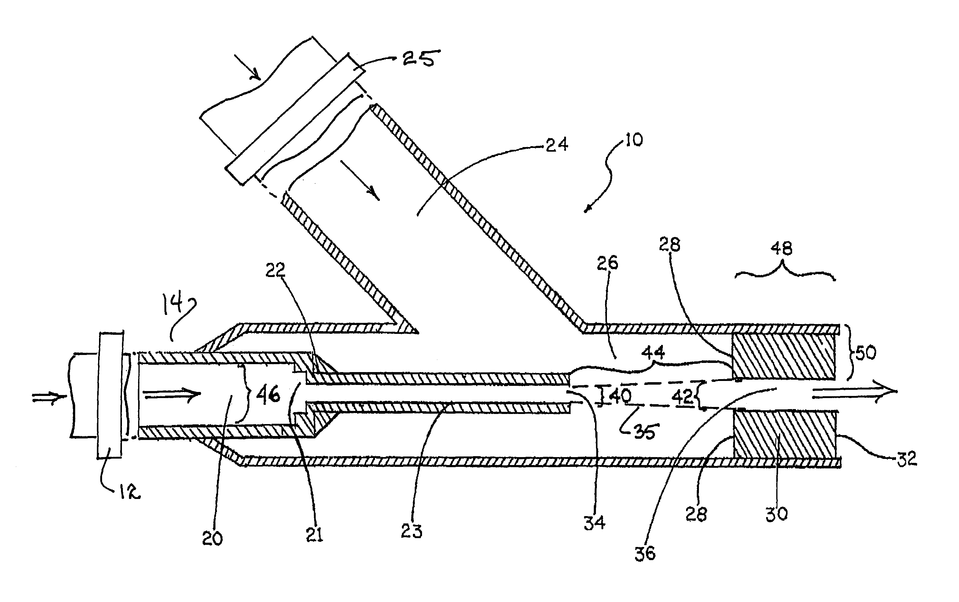
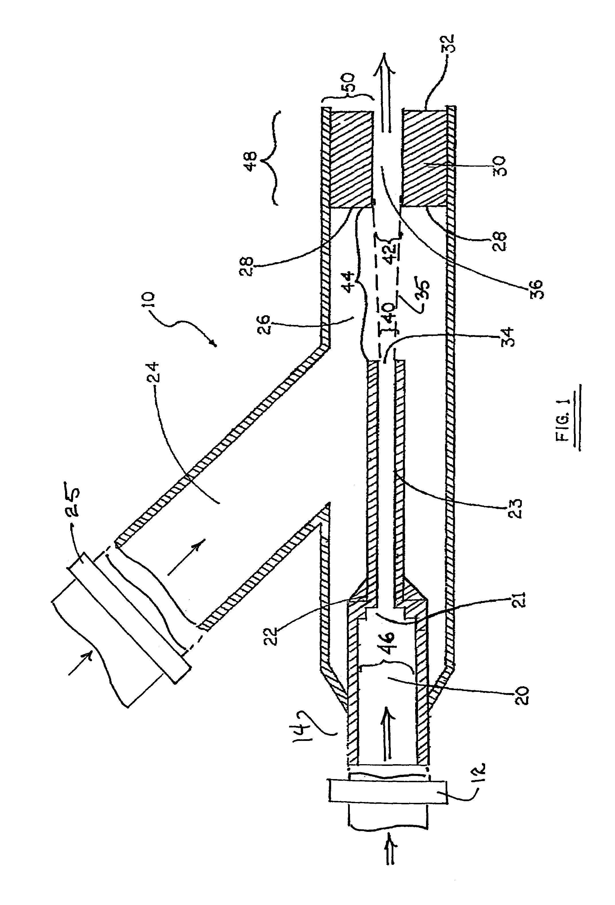
[0044]In a preferred embodiment, the distance 44 from the exit of the reduction means 34 to the exit cylinder entrance face 28 is 1 to 10 times greater than the diameter of the exit cylinder 42 depending on the motive flow pressure. In addition, the length of the exit cylinder 30 is also dependent on the motive flow pressure and is 1 to 10 times greater than the diameter 42 of the exit cylinder 30. It is also desirable that the distance 50 from the inside of the exit channel 36 to the outer edge of the exit cylinder 30 be equal to or greater than the radius of the diameter 42 of the exit channel 36. It is also important to note that the entrance face 28 of the exit cylinder 30 as well as the exit face 32 of the exit cylinder 30 should be substantially perpendicular to the flow of the liquid stream.

example 2

[0045]With reference again to FIG. 1, in an alternative embodiment, the vent line 24 can be connected to an alternative gas source 25. Such an alternative gas source can include pressure pumps or other means whereby a gas is delivered under pressure or otherwise for introduction into the liquid. For example, when used in a pool or other body of water in which chlorination is desired, a chlorine gas supply can be connected in fluid communication with the vent line 24. In the alternative, the chlorine gas supply can be directly connected in fluid communication with the mixing chamber 26 at an alternate entrance. Either embodiment allows for the improved mixture of chlorine gas with water.

example 3

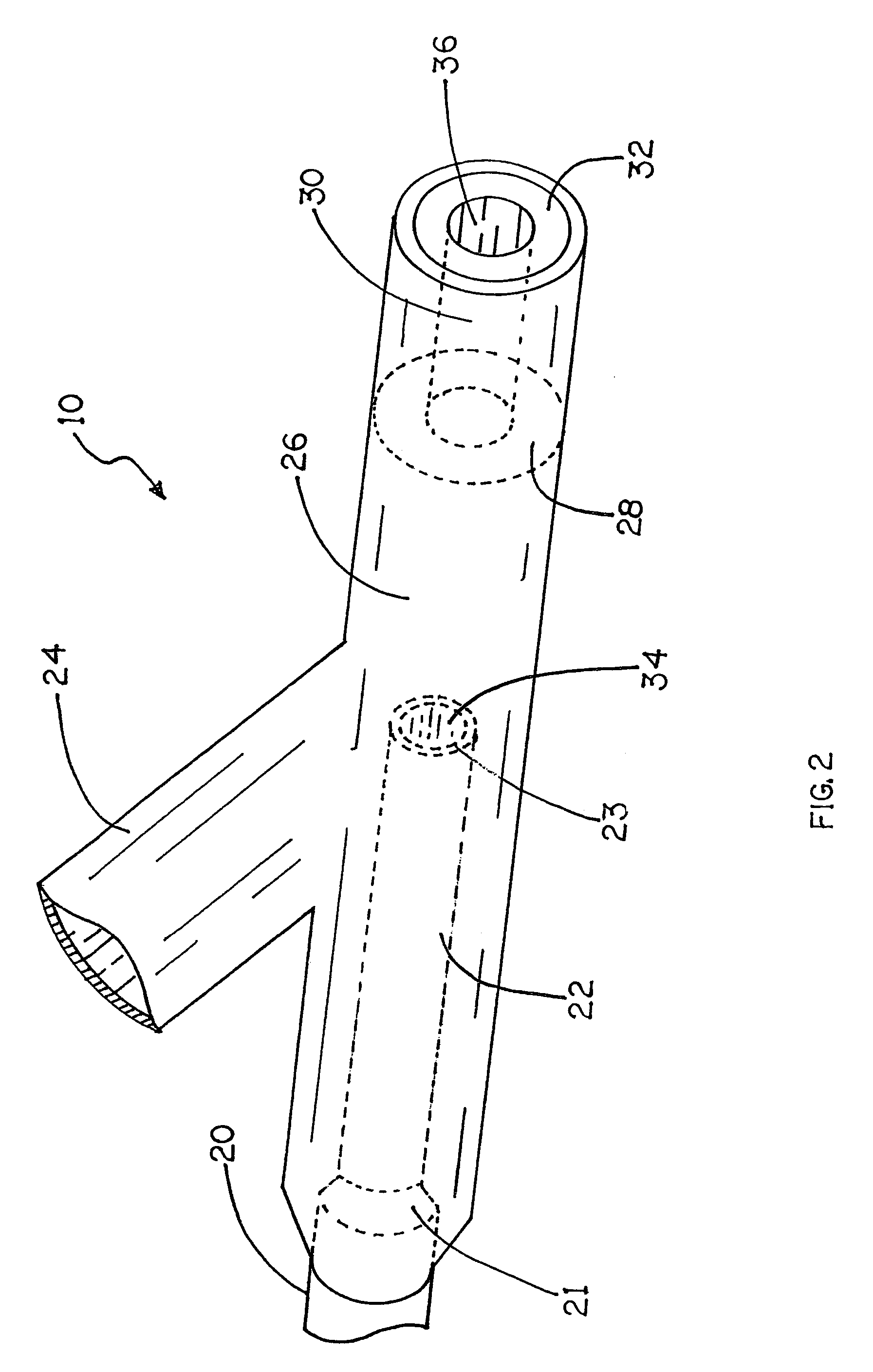
[0046]In a still further embodiment, the stepped internal nozzle 22 is not concentrically disposed in the mixing chamber 26. The stepped internal nozzle 22 may be disposed in any position in the mixing chamber 26 provided the liquid stream passing therefrom enters the exit channel 36 unobstructed.


PUM

PropertyMeasurementUnit
depthaaaaaaaaaa
pressureaaaaaaaaaa
exit diameteraaaaaaaaaa

Abstract

A liquid feed line includes a stepped internal nozzle and an exit diameter smaller than the diameter of the liquid feed line. The stepped internal nozzle desirably introduces hydrodynamics or hydraulic waves for the fluid, with the number of steps selected based on the pressure of the motive flow. By limiting the length of the stepped internal nozzle cylinder, a desirable splayed liquid stream is formed within a mixing chamber in fluid communication with a vent line. An exit cylinder in fluid communication with the mixing chamber includes a channel through which an aerated liquid stream of fluid passes. The entrance and exit faces forming the channel are substantially perpendicular to the fluid flow with the channel having a generally uniform dimension, neither converging nor diverging, and a diameter 1 to 10 times greater, depending on the pressure of the motive flow, than the exit to the internal nozzle.

Description

CROSS-REFERENCE TO RELATED APPLICATIONS[0001]This application is a Continuation in Part of U.S. application Ser. No. 10 / 427,545, filed May 1, 2003 and issuing as U.S. Pat. No. 6,986,506, and claims the benefit of U.S. Provisional Application No. 60 / 622,578, filed Oct. 27, 2004, the disclosures of which are hereby incorporated by reference herein in their entireties, and all commonly owned.FIELD OF THE INVENTION[0002]The invention generally relates to devices and methods for introducing a gas into a liquid or degassing of a liquid, and more particularly to aeration of water.BACKGROUND OF THE INVENTION[0003]Bodies of water, such as lakes, ponds, canals, pools, and the like suffer from the growth of algae and other undesirable aquatic biota that lead to the depletion of oxygen and other elements required to sustain life therein. In nature, air is generally absorbed in a body of water through the agitation of surface waters resulting from waves and wind. Smaller bodies of water in stagn...

Claims


Application Information

Patent Timeline
Patent Type & Authority Patents(United States)
IPC IPC(8): B01F3/04
CPCB01F3/0446B01F5/0415B01F5/0428B01F5/0689B01F5/0682Y10S261/75B01F2215/0052B01F23/232B01F25/3121B01F25/31242B01F25/45211B01F25/45B01F2101/305B01F23/2326
Inventor CHAPMAN, TEDDIE C.TERRY, III, JAMES C.
Owner CHAPMAN TEDDIE C
Why Eureka
Try Eureka