Light guide plate with v-shaped grooves and backlight module incorporating same

a technology of light guide plate and v-shaped groove, which is applied in the direction of lighting and heating apparatus, instruments, mechanical equipment, etc., can solve the problems of non-uniform illumination provided by the emitting surface b>4/b>, waste of refracted light beams, etc., and achieve the effect of improving the utilization of light beams

Inactive Publication Date: 2007-01-02
INNOLUX CORP
View PDF6 Cites 54 Cited by
  • Summary
  • Abstract
  • Description
  • Claims
  • Application Information

AI Technical Summary

Benefits of technology

[0012]Because a side of each V-shaped groove is a curved surface, and at least one part of the curved surface is wave-shaped, when the light beams come to the V-shaped groove, the incident angles are different. By configuring the bending of the curved side of the V-shaped groove, the light guide plate can configure the incident angle, and make the incident angle is enough big, and make the light beams reflected from the side and not refracted. Thus, the utilization of the light beams is improved.

Problems solved by technology

The refracted light beams are wasted.
Thus the overall utilization of light beams by the light guide plate is lowered, and illumination provided by the emitting surface 4 is liable to be non-uniform.

Method used


Image

  • Light guide plate with v-shaped grooves and backlight module incorporating same
  • Light guide plate with v-shaped grooves and backlight module incorporating same
  • Light guide plate with v-shaped grooves and backlight module incorporating same

Examples


first embodiment

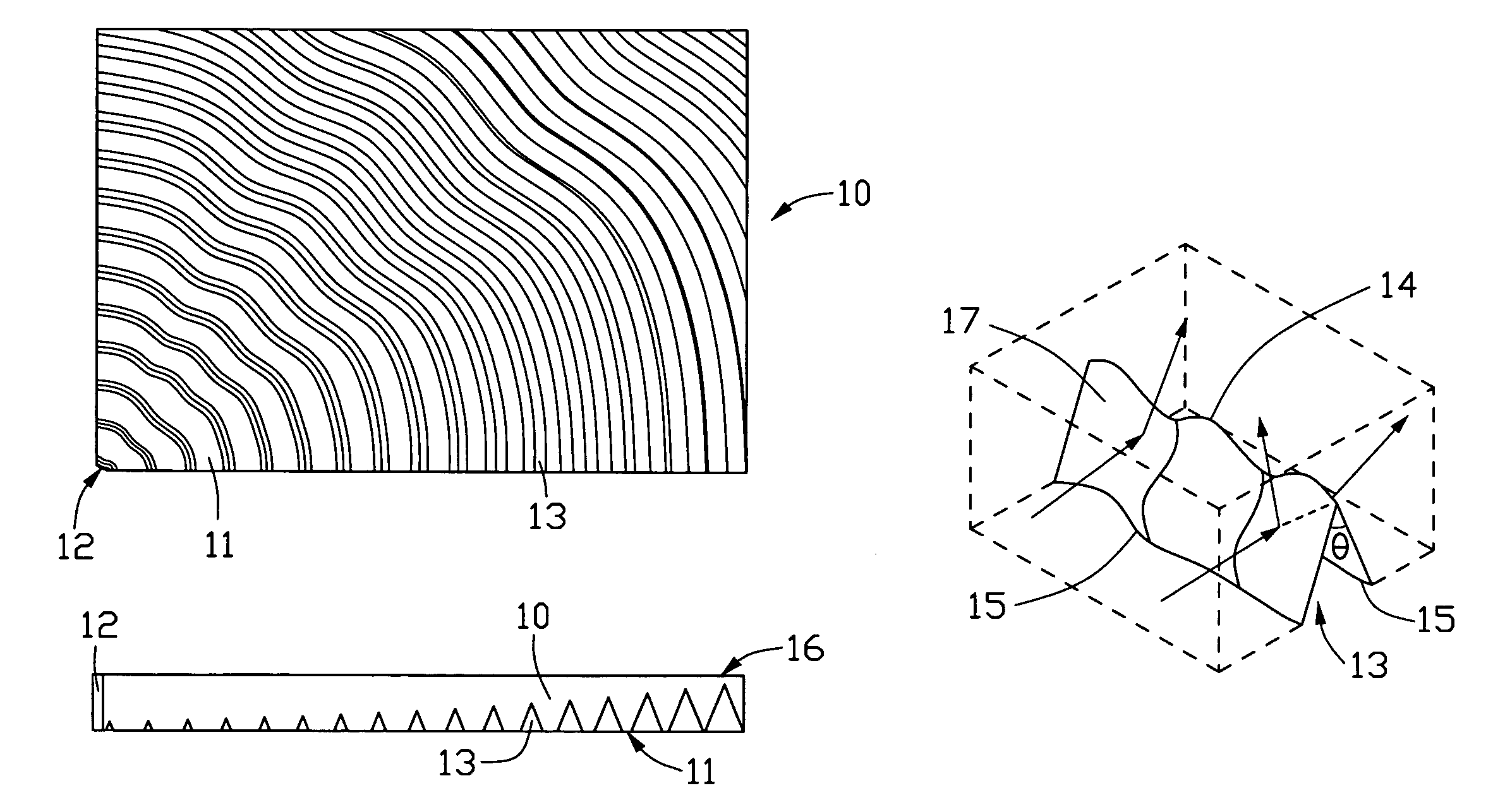
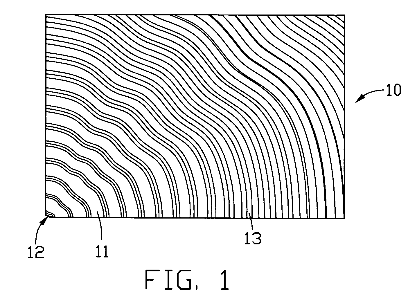
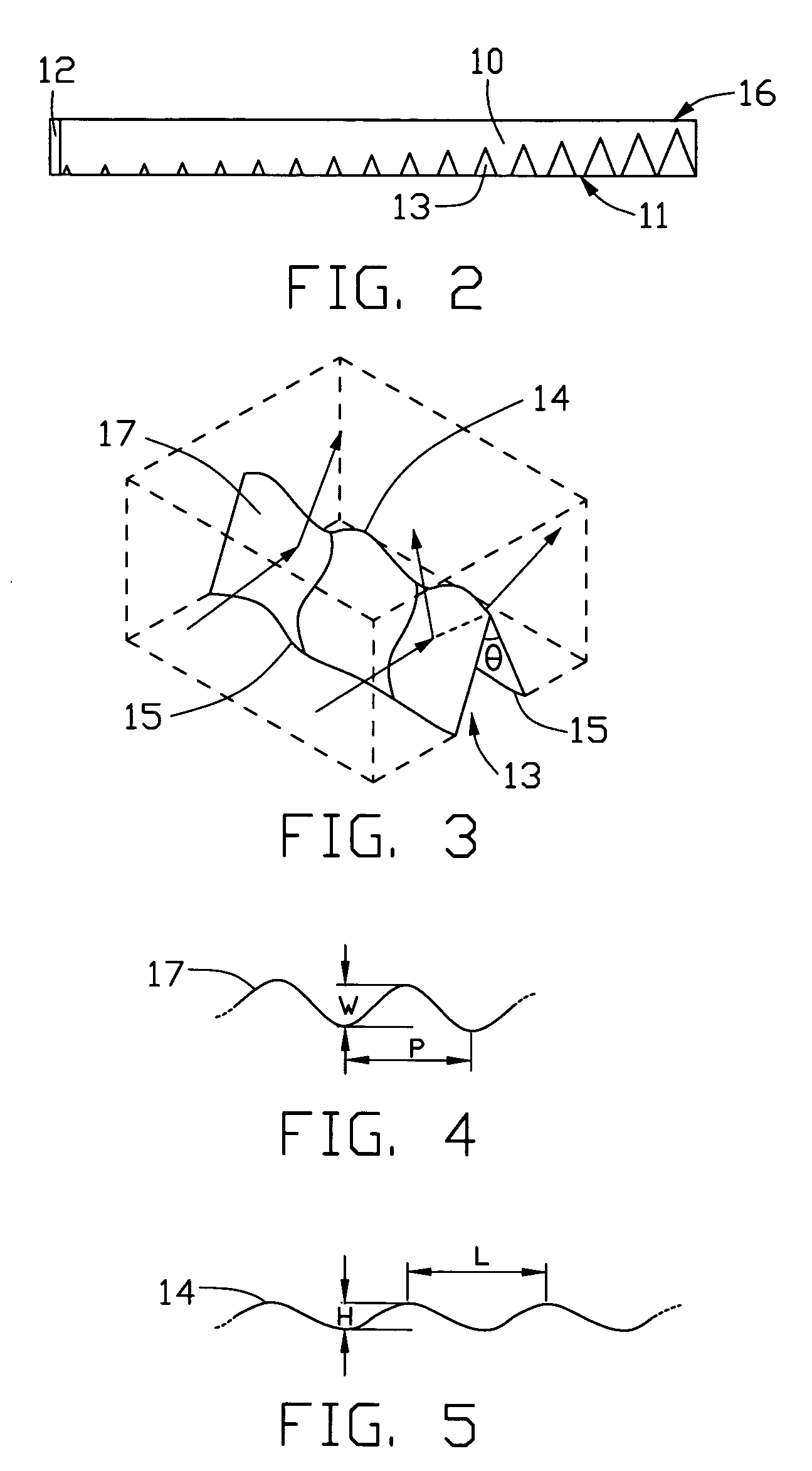
[0028]Referring to FIG. 1 and FIG. 2, a light guide plate 10 according to the present invention is shown. The light guide plate 10 includes an incident surface 12, a bottom surface 11, and an emitting surface 16. The incident surface 12 is at a corner of the light guide plate 10, and adjoins the bottom surface 11. The emitting surface 16 is opposite to the bottom surface 11. The bottom surface 11 has a plurality of parallel, V-shaped grooves 13. The V-shaped grooves 13 become progressively more densely arranged along a direction away the incident surface 12. In addition, heights of the V-shaped grooves 13 become progressively greater along a direction away the incident surface 12.

[0029]Referring to FIG. 3 through FIG. 5, part of a V-shaped groove 13 according to the first embodiment is shown. Each V-shaped groove 13 defines two sides 17, a top line 14 where the sides 17 intersect, two bottom lines 15 at bottom extremities of the sides 17 respectively, and an angle θ between the side...

second embodiment

[0032]Referring to FIG. 6 and FIG. 7, a light guide plate 20 according to the present invention is shown. The light guide plate 20 has an incident surface 22 and a bottom surface 21. The incident surface 22 is at a corner of the light guide plate 20. The bottom surface 21 has a plurality of parallel, V-shaped grooves 23. The V-shaped grooves 23 are arc-shaped. For each V-shaped groove 23, every point along an apex of the V-shaped groove 23 is substantially equidistant from the incident surface 22. The V-shaped grooves 23 all have a same width and a same height. More particularly, a density of the V-shaped grooves 23 is uniform in a direction away from the incident surface 22.

[0033]FIG. 8 illustrates part of a V-shaped groove 23 according to the second embodiment. The V-shaped groove 23 has two sides, a top line 24, and two bottom lines 25. Unlike the V-shaped groove 13 of the first embodiment, the bottom lines 25 of the V-shaped groove 23 are both arc-shaped.

third embodiment

[0034]Referring to the FIG. 9, a light guide plate 30 according to the present invention is shown. The light guide plate 30 has an incident surface 32 and a bottom surface 31. The incident surface 32 is at a corner of the light guide plate 30. The bottom surface 31 has a plurality of parallel, V-shaped grooves 33. A density of the V-shaped grooves 33 is uniform in a direction away from the incident surface 32.

[0035]FIG. 10 illustrates part of a V-shaped groove 33 according to the third embodiment. The V-shaped groove 33 has two sides, a top line 34, and two bottom lines 35. Unlike the V-shaped groove 13 of the first embodiment, the bottom lines 35 of the V-shaped groove 33 are both rectilinear.

[0036]Referring to the FIG. 1, a light guide plate 40 according to the fourth embodiment of the present invention is shown. Unlike the light guide plate 10 of the first embodiment, an incident surface 42 of the light guide plate 40 is at a main side of the light guide plate 40. A plurality of ...


PUM


Abstract

A light guide plate (10) of a preferred embodiment includes: an incident surface (12) for receiving incident light beams from a corresponding light source; an emitting surface (16); and a bottom surface (11) opposite to the emitting surface. The bottom surface defines a plurality of V-shaped grooves. A side (17) of each V-shaped groove is a curved surface, and at least one part of the curved surface is wave-shaped. The light guide plate can improve the utilization of light beams, reduce wastage of light beams and configure the uniformity of luminance.

Description

BACKGROUND OF THE INVENTION[0001]1. Field of the Invention[0002]The present invention relates to a light guide plate employed in a backlight module, and particularly to a light guide plate having V-shaped grooves configured for high and uniform brightness.[0003]2. Description of Related Art[0004]Because a liquid crystal display (LCD) device has the merits of being thin, light in weight, and drivable by a low voltage, it is extensively employed in various electronic devices.[0005]A liquid crystal panel of an LCD device cannot itself emit light beams. Therefore a typical liquid crystal panel uses a backlight module to provide the needed illumination. The backlight module has a light source and a light guide plate. The light source emits the light beams to the light guide plate, which then transmits the light beams to illuminate liquid crystal panel.[0006]Referring to FIG. 14, one kind of typical backlight module is shown. The backlight module 1 comprises a light guide plate 2 and a li...

Claims


Application Information

Patent Timeline
Patent Type & Authority Patents(United States)
IPC IPC(8): F21V8/00
CPCG02B6/0061G02B6/0038
Inventor TENG, CHING-HUNGYANG, CHIU-LIENPANG, JIA-PANG
Owner INNOLUX CORP
Why Eureka
Try Eureka