Wall-mounting image processing apparatus

Inactive Publication Date: 2007-01-02
ROHM CO LTD
View PDF14 Cites 4 Cited by
  • Summary
  • Abstract
  • Description
  • Claims
  • Application Information

AI Technical Summary

Benefits of technology

[0006]It is an object of the present invention to provide a wall-mounting image processing apparatus which eliminates or reduces problems of the prior art described above.

Problems solved by technology

However, in the above-described facsimile machine, the platen rollers P1, P2 are disposed so as to sandwich the image reading / writing head Y, so that the platen rollers P1 and P2 are bulky in the thickness direction of the image reading / writing head Y. Therefore, in the prior art described above, it is not possible to sufficiently reduce the thickness of the wall-mounting image processing apparatus.

Method used


Image

  • Wall-mounting image processing apparatus
  • Wall-mounting image processing apparatus
  • Wall-mounting image processing apparatus

Examples


first embodiment

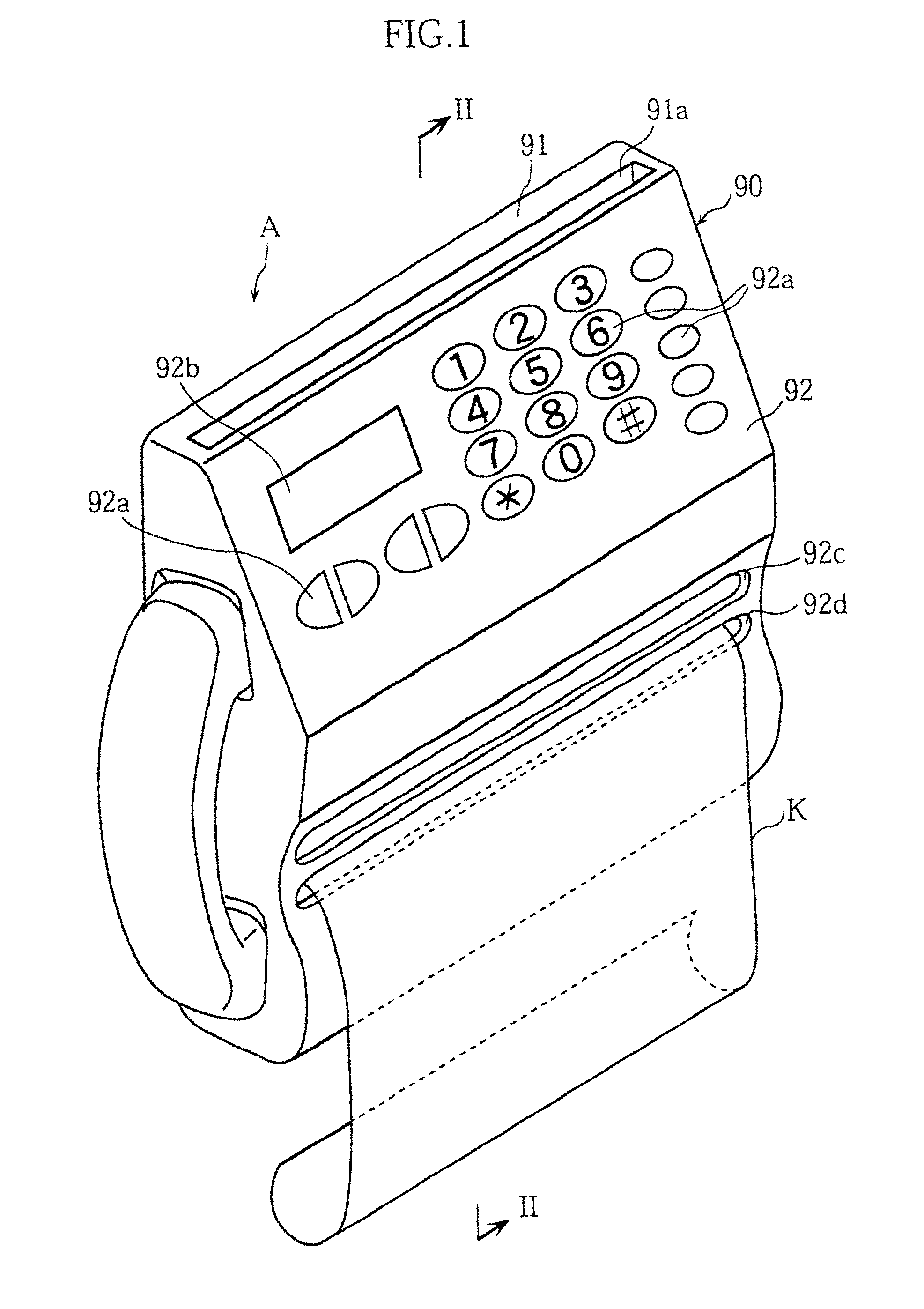
[0052]FIGS. 1 through 4 illustrate the present invention. In these figures, the elements which are identical or similar to those of the prior art are designated by the same reference signs as those used for the prior art.

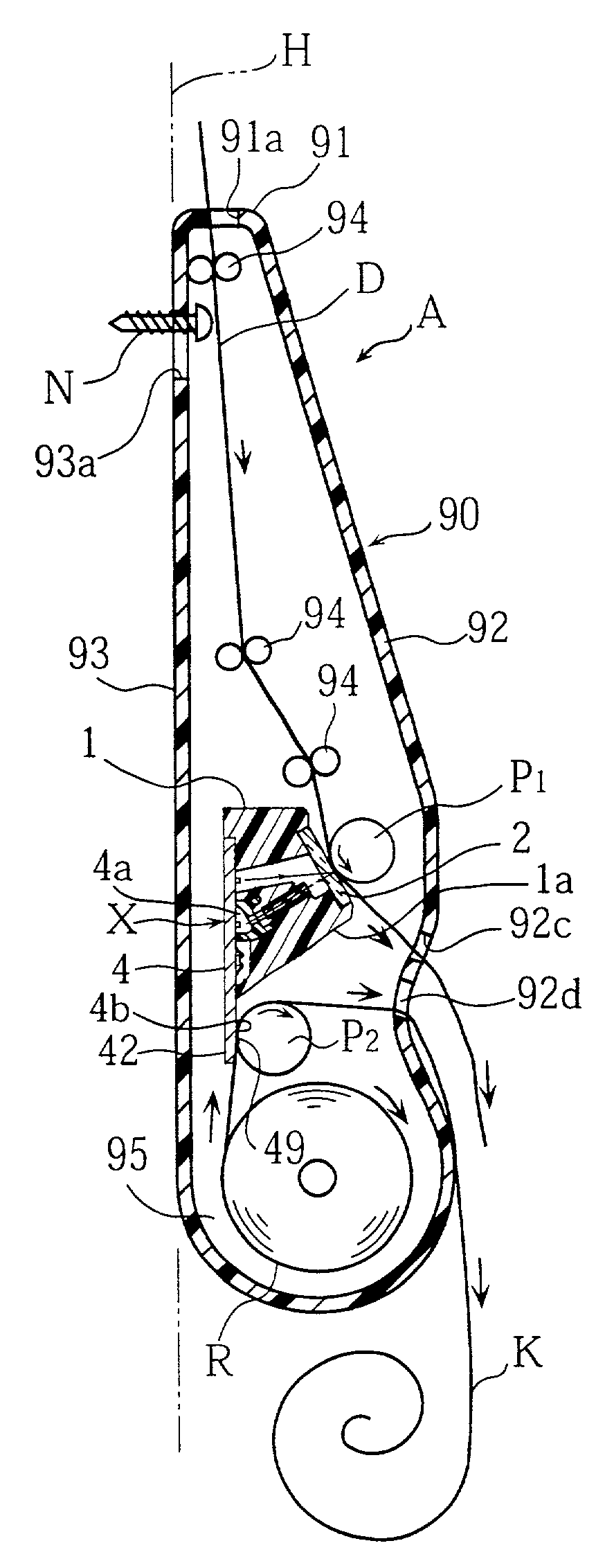
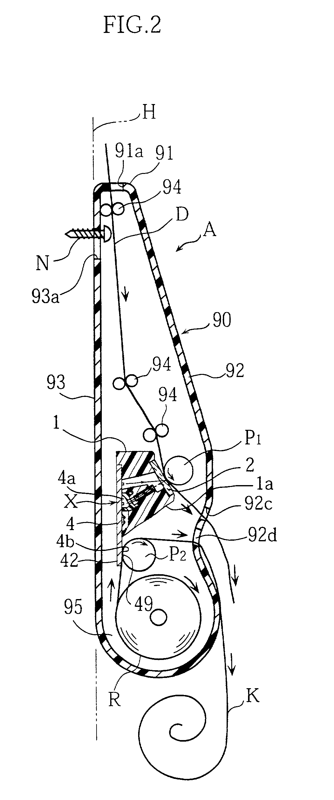
[0053]Referring to FIG. 2, a wall-mounting image processing apparatus A in accordance with the first embodiment comprises a machine housing 90, an image reading / writing head X disposed in the machine housing 90, a platen roller P1 for a document and a platen roller P2 for a recording paper.

[0054]As clearly shown in FIGS. 3 and 4, the image reading / writing head X comprises a head case 1, a transparent cover 2, a lens array 5, a reflection preventing member 6, a substrate 4 and other parts which will be described below.

[0055]The substrate 4, which may be made of ceramic material for example, is in the form of an elongated rectangular plate. The substrate 4 has an obverse surface (one surface) 4A which is provided with a plurality of light sources 3, a plurality of ima...

fourth embodiment

[0079]FIGS. 7 through 10 illustrate the present invention.

[0080]As clearly shown in FIGS. 7 and 8, a wall-mounting image processing apparatus Aa in the fourth embodiment includes a machine housing 90A which comprises a main body 95, a first lid 96 and a second lid 97. The main body 95 is in the form of a container having a predetermined depth and has an opening at its front side. The main body internally accommodates an image reading / writing head Xc. The first lid 96 functions to close an upper portion of the front opening of the main body 95. The first lid is supported, at its upper portion, on the main body 95 via a shaft 98a for rotation about the shaft 98a in the direction indicated by an arrow Na. The first lid 96 has an obverse surface which is provided with operation switches 92a and a display portion 92b. Between respective upper edges of the first lid 96 and the main body 95 is provided an elongated narrow clearance which serves as a document inserting port 91a. The second ...


PUM


Abstract

A wall-mounting image processing apparatus (A) includes a machine housing (90) mounted on a substantially vertical wall surface (H), and an image reading / writing head (X) disposed in the machine housing. The image reading / writing head (X) includes a substrate (4) having one surface (4A) on which a plurality of light receiving elements (4a) are arranged in a row. Part of said one surface (4A) forms an excess surface (49) projecting laterally from a head case (1), and the printing elements (4b) are arranged on the excess surface (49).

Description

TECHNICAL FIELD[0001]The present invention relates to a wall-mounting image processing apparatus which, in use, is mounted on a wall surface of a house for example. More particularly, the present invention relates to a wall-mounting image processing apparatus having both an image reading function and an image printing function.BACKGROUND ART[0002]An example of image processing apparatus is a wall-mounting facsimile machine, which, in use, is mounted on a wall surface of a house. In use of such a wall-mounting facsimile machine, it is desired that the facsimile machine does not project greatly from the wall surface. Accordingly, there is a higher need for overall thickness reduction with respect to a wall-mounting facsimile machine than other type of facsimile machine used on a table or desk.[0003]A prior art facsimile machine has the structure as shown in FIG. 11, for example, in which an image reading / writing head is accommodated in a machine housing. The illustrated image reading / ...

Claims


Application Information

Patent Timeline
IPC IPC(8): B41J29/00H04N1/024H04N1/00H04N1/031H04N1/12
CPCH04N1/00519H04N1/00525H04N1/024H04N1/02463H04N1/031H04N1/02427H04N1/12H04N1/00
Inventor FUJIMOTO, HISAYOSHIONISHI, HIROAKITAKAKURA, TOSHIHIKOIMAMURA, NORIHIRO
Owner ROHM CO LTD
Why Eureka
Try Eureka