Communication apparatus and protocol processing method
Inactive Publication Date: 2008-06-26
FUJITSU LTD
View PDF7 Cites 27 Cited by
Summary
Abstract
Description
Claims
Application Information
AI Technical Summary
This helps you quickly interpret patents by identifying the three key elements:
Problems solved by technology
Method used
Benefits of technology
Benefits of technology
[0028]Embodiments of the present invention provide protocol technologies for sending and receiving network topology information inclu
Problems solved by technology
LSPs on a link of this type will be lost if any of the links it is protecting fails.
LSPs on a link of this type will be lost if the link fails.
However, there is one problem in using a synchronous optical network / synchronous digital hierarchy (SONET / SDH) path in a BLSR as a link for setting up an LSP.
When the NUT line fails, the traffic flowing through the NUT line is lost.
With the current routing protocol standards for GMPLS, however, it is not possible to advertise the protection type regarding redundancy for each of the SONET / SDH lines in a link.
However, with the topology information shown in FIG. 5, for example, it is not possible to set up a low-cost LSP using PCA lines since only one protection type is provided for each link.
Also, although it is necessary to use the same type of synchronous transport signal (STS) channels of SONET (or the same type of synchronous transport module (STM) channels of SDH) when setting up an LSP on normal lines in a BLSR, it is not possible to advertise STS (or STM) channel information with the current GMPLS standards.
Therefore, with the current OSPF-TE or the MPLS / GMPLS standards, it is not possible to select the same type of STS channels for an LSP to be set up on normal lines at the route calculation stage, and it is only possible to select the same type of STS channels when setting up the LSP by using a signaling protocol.
However, if the proprietary type number is assigned to a new TLV type in a standard in the future, the original TLV becomes unusable.
If different types of TLVs are assigned to the same type number, it causes a malfunction of a network apparatus.
Therefore, defining an original TLV is not an appropriate way to solve the problem.
The above problem applies not only to a case where an LSP is set up in a network including a BLSR but also to a case where an LSP is set up in a network having any type of redundant configuration.
Method used
Image
Click on the blue label to locate the original text in one second.
Reading with bidirectional positioning of images and text.
Examples
first example
[0057]FIG. 9 is a flowchart showing a first exemplary link information sending process by the communication apparatus 10. This process is performed by the routing protocolprocessing unit 22 of the communication apparatus 10.
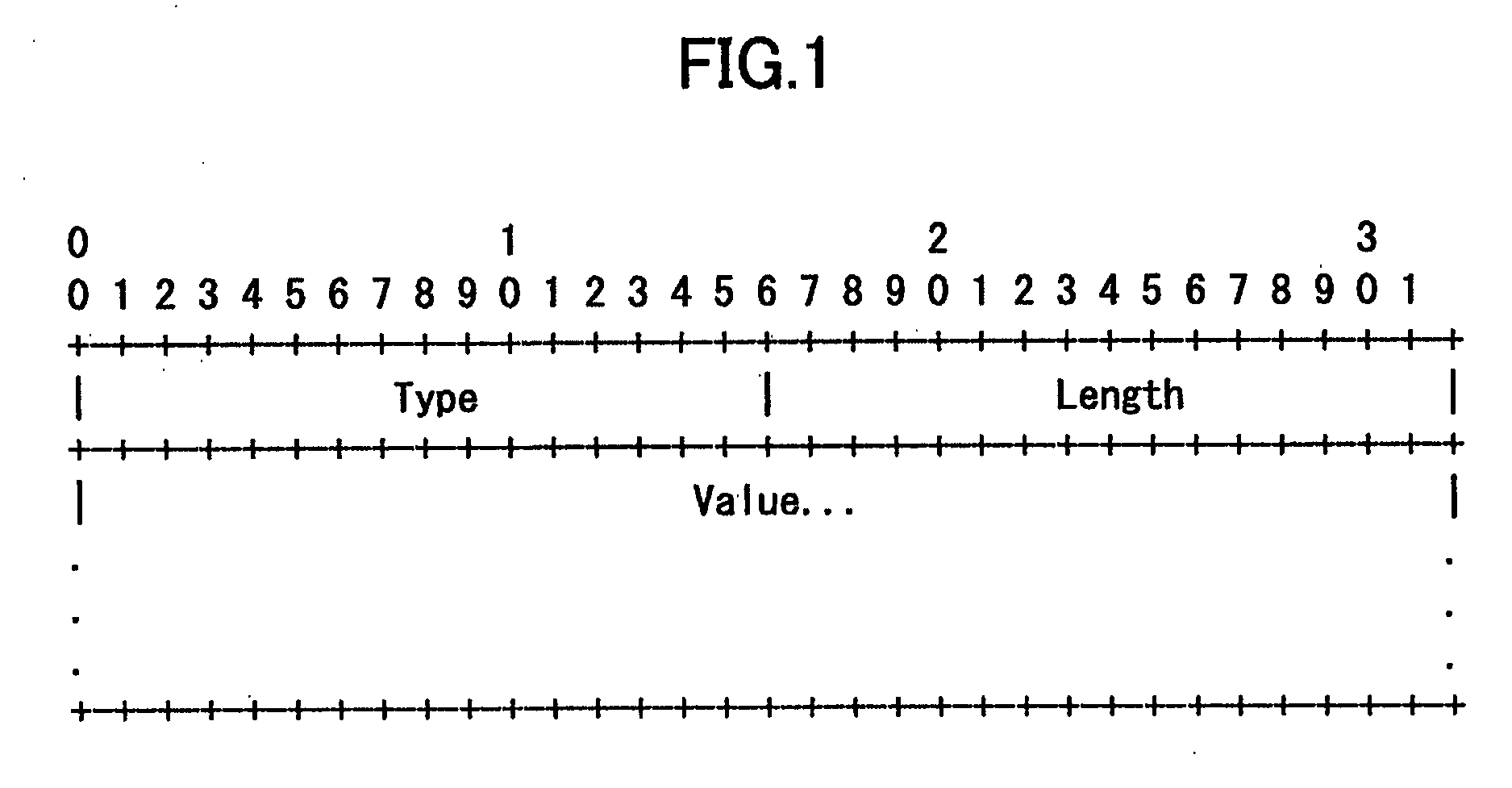
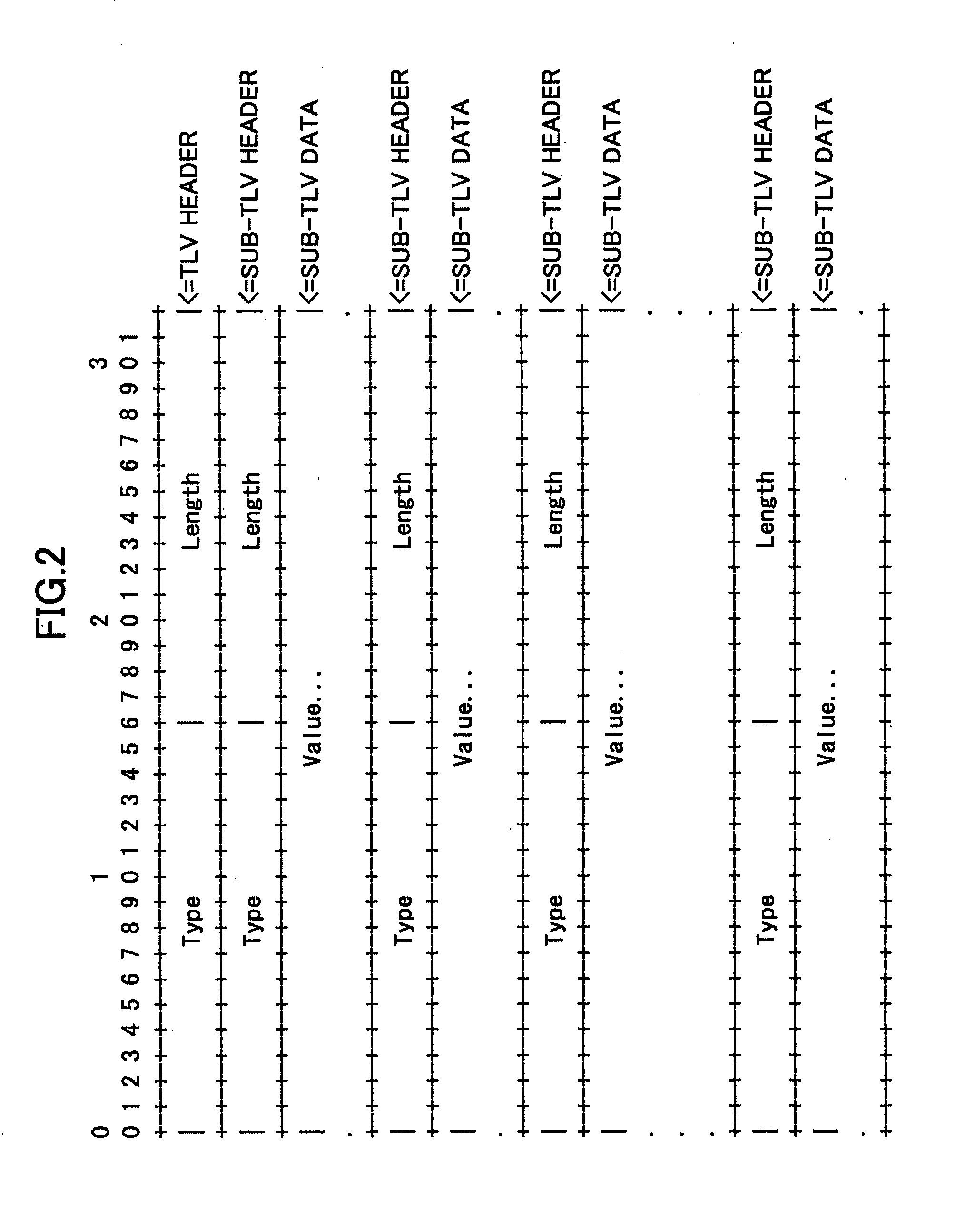
[0058]In step 1, the communication apparatus 10 generates a TLV frame. In step 2, the communication apparatus 10 generates a TLV of LSA type 10 (opaque LSA). In step 3, the communication apparatus 10 generates sub-TLV 1, sub-TLV 2, sub-TLV 3, sub-TLV 4, sub-TLV 5, sub-TLV 6, sub-TLV 7, sub-TLV 8, sub-TLV 9, sub-TLV 11, sub-TLV 14, sub-TLV 15, and sub-TLV 16. The number following each sub-TLV indicates the type of the sub-TLV. Steps 1 through 3 conform to the current OSPF-TE. It is not always necessary to generate all of the sub-TLVs mentioned above. In step 43, sub-TLVs required by the current OSPF-TE (mandatory sub-TLVs) and sub-TLVs necessary for the current process are generated.
[0059]In step 4, the communication apparatus 10 generates sub-TLV 9 (1) (the numb...
second example
[0081]A second exemplary link information sending process and a second exemplary link information receiving process by the communication apparatus 10 are described below. FIG. 14 is a flowchart showing a second exemplary link information sending process by the communication apparatus 10.
[0082]In step 41, the communication apparatus 10 generates a TLV frame. In step 42, the communication apparatus 10 generates a TLV of LSA type 10 (opaque LSA). In step 43, the communication apparatus 10 generates sub-TLV 1, sub-TLV 2, sub-TLV 3, sub-TLV 4, sub-TLV 5, sub-TLV 6, sub-TLV 7, sub-TLV 8, sub-TLV 9, sub-TLV 11, sub-TLV 14, sub-TLV 15, and sub-TLV 16. As in the first example, steps 41 through 43 conform to the current OSPF-TE. It is not always necessary to generate all of the sub-TLVs mentioned above. In step 43, sub-TLVs required by the current OSPF-TE and necessary for the current process are generated.
[0083]In step 44, as in step 4 of the first example, the communication apparatus 10 gen...
PUM
Abstract
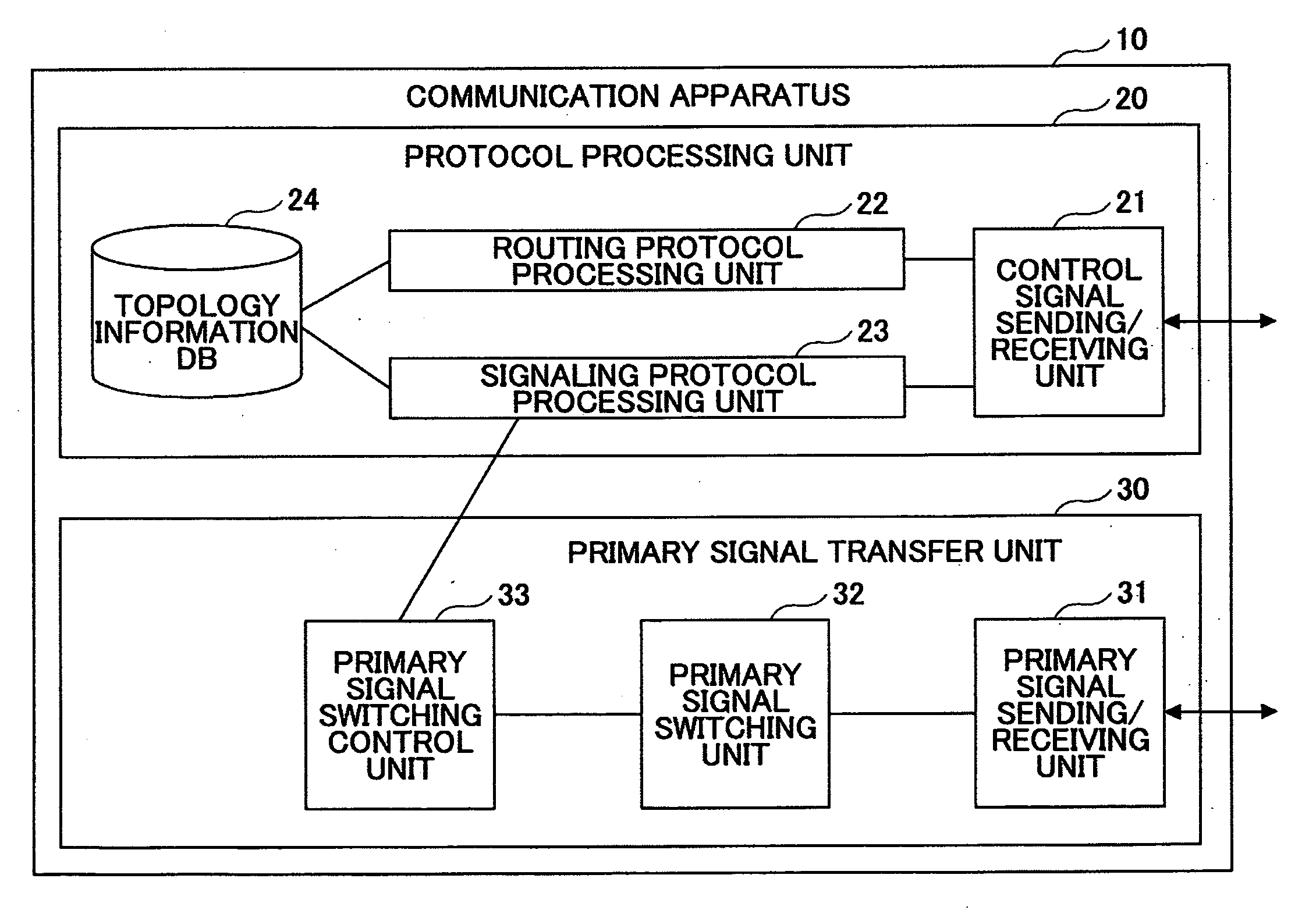
A disclosed communication apparatus includes a protocol processing unit configured to send and receive link information on a link in a network having a redundant configuration according to a protocol, to build topology information of the network from the link information, and to set up a path in the network based on the topology information. The protocol processing unit includes a link information advertising unit configured to advertise the link information including, for each of protection types of the link, information used to set up the path, a topology information storing unit configured to store the topology information, and a link information receiving unit configured to receive the link information and to store the received link information in the topology information storing unit.
Description
CROSS-REFERENCE TO RELATED APPLICATIONS[0001]The present application is based upon and claims the benefit of priority from the prior Japanese Patent Application No. 2006-349993 filed on Dec. 26, 2006, with the Japanese Patent Office, the entire contents of which are incorporated herein by reference.BACKGROUND OF THE INVENTION[0002]1. Field of the Invention[0003]The present invention generally relates to technologies for sending and receiving network topology information including redundancy information between nodes using a routing protocol for generalized multiprotocol label switching (GMPLS).[0004]2. Description of the Related Art[0005]A technology called multiprotocol label switching (MPLS), in which IP packets are routed based on labels, has become widely used. Also, a technology called generalized multiprotocol label switching (GMPLS) is drawing attention. In GMPLS, the idea of “labels” used for routing IP packets in MPLS is generalized and adapted for other networking technolo...
Claims
Application Information
Patent Timeline
Application Date:The date an application was filed.
Publication Date:The date a patent or application was officially published.
First Publication Date:The earliest publication date of a patent with the same application number.
Issue Date:Publication date of the patent grant document.
PCT Entry Date:The Entry date of PCT National Phase.
Estimated Expiry Date:The statutory expiry date of a patent right according to the Patent Law, and it is the longest term of protection that the patent right can achieve without the termination of the patent right due to other reasons(Term extension factor has been taken into account ).
Invalid Date:Actual expiry date is based on effective date or publication date of legal transaction data of invalid patent.

