Tank feed through structure for a radar level gauge

Active Publication Date: 2014-09-18
ROSEMOUNT TANK RADAR
View PDF26 Cites 30 Cited by
  • Summary
  • Abstract
  • Description
  • Claims
  • Application Information

AI Technical Summary

Benefits of technology

[0006]It is an object of the present invention to mitigate these problems and provide a radar level gauge

Problems solved by technology

This leads to a great number of individual parts that need to be manufactured and stored by suppli

Method used


Image

  • Tank feed through structure for a radar level gauge
  • Tank feed through structure for a radar level gauge
  • Tank feed through structure for a radar level gauge

Examples


Embodiment Construction

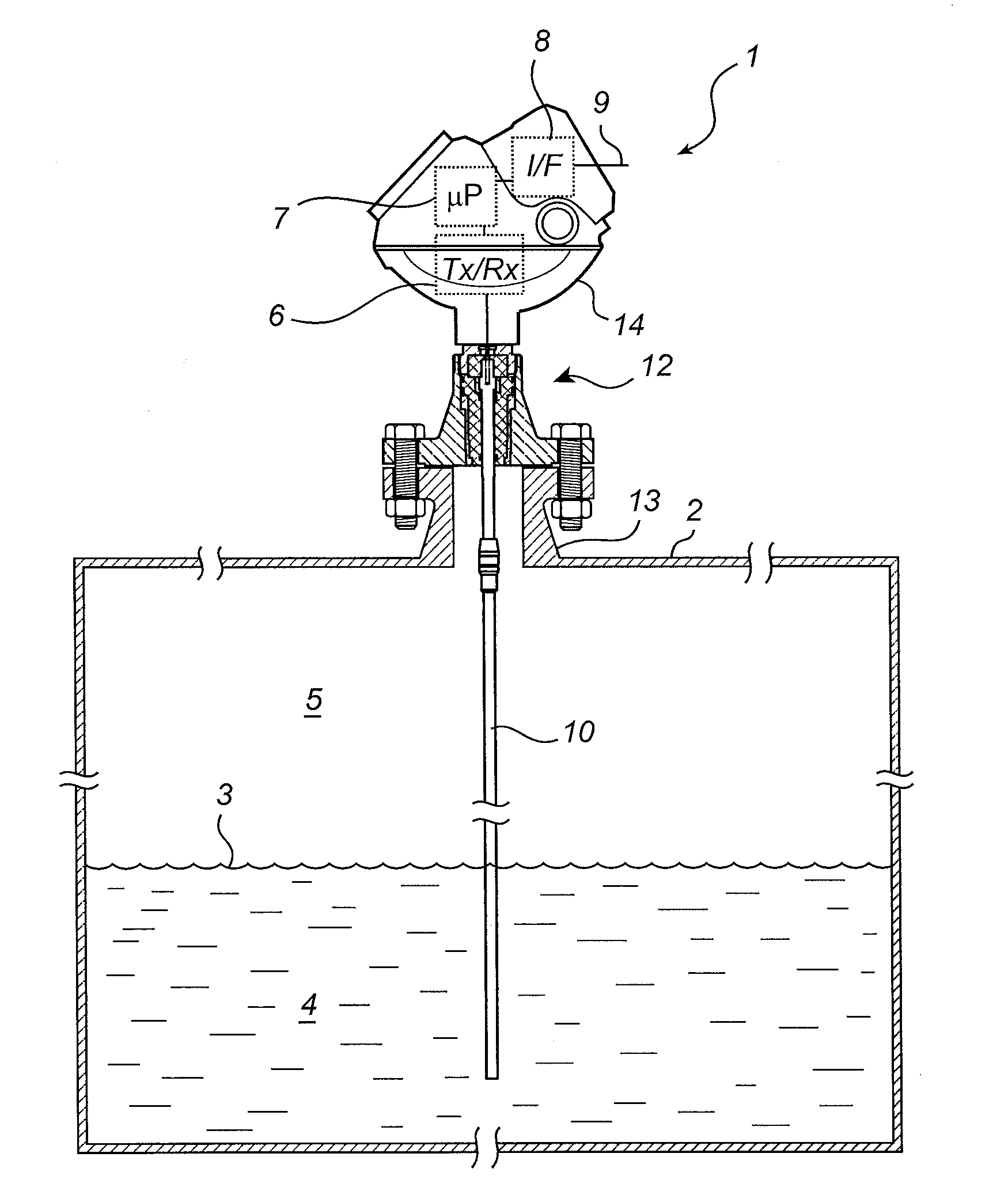
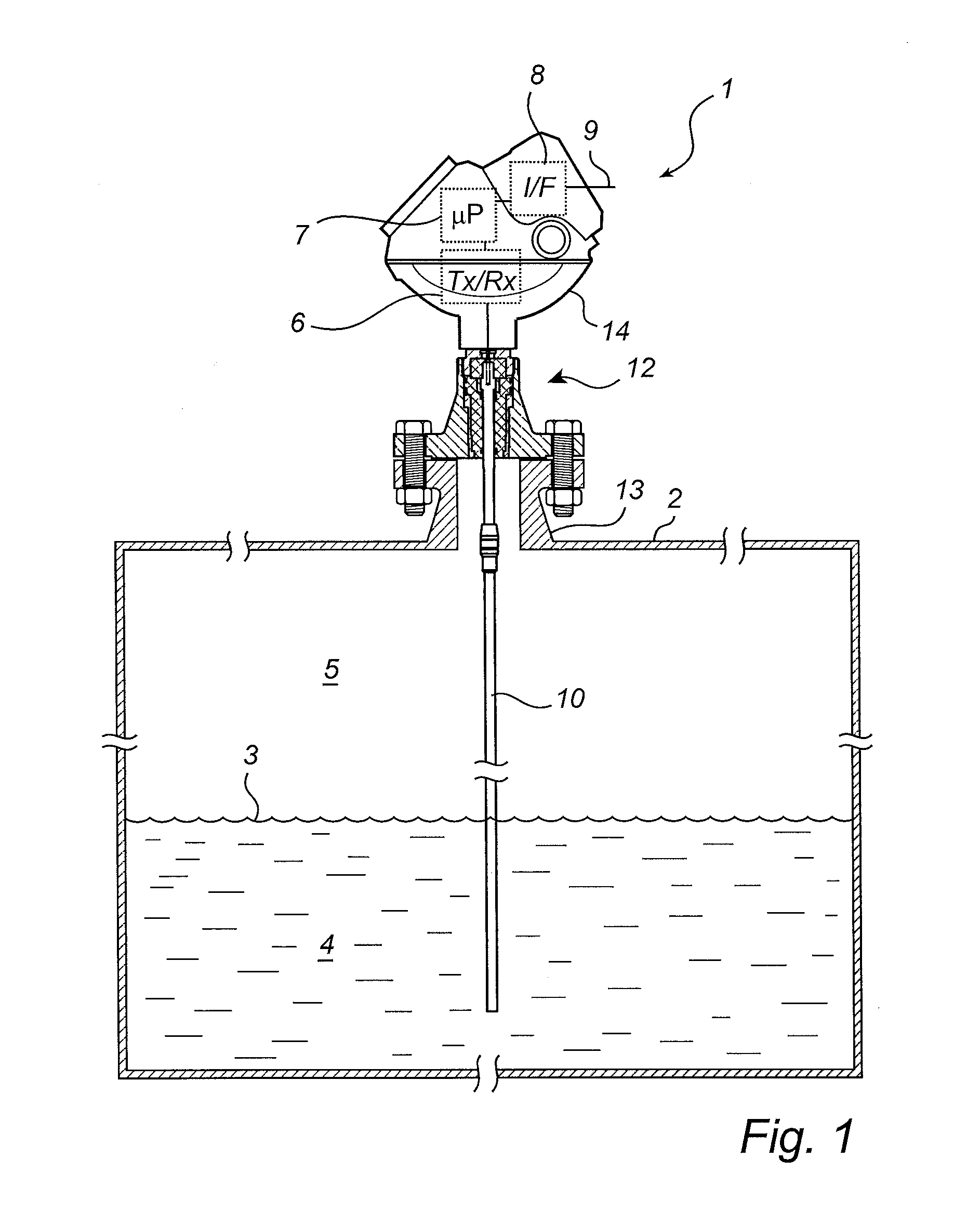
[0023]FIG. 1 shows a schematic drawing of a radar level gauge (RLG) 1 according to an embodiment of the present invention. The RLG 1 is mounted on a tank 2, and arranged to perform measurements of a process variable such as the level L of an interface 3 between two materials 4, 5 in the tank 2. Typically, the first material is a liquid 4 stored in the tank, e.g. gasoline, while the second material is air or other atmosphere 5 in the tank. In some applications, the tank is a very large metal tank (diameter in the order of 10 m).

[0024]The radar level gauge 1 includes transceiver circuitry 6, processing circuitry 7 and a signal and power interface 8, all enclosed in a housing 14. The transceiver circuitry 6 is electrically connected to a signal propagating device 10 extending into the tank 2. The signal propagating device 10 is arranged to act as an adapter, transmitting electromagnetic waves into the tank 2 to be reflected by the interface, here the surface 3 of the product 4 in the t...


PUM

PropertyMeasurementUnit
Electrical conductoraaaaaaaaaa

Abstract

A radar level gauge using electromagnetic waves for determining a filling level of a product in a tank, comprising a transceiver, processing circuitry, a signal propagating device and a tank feed through structure. The tank feed through structure includes a fixed tank connection arranged to be secured to the tank, a tank connection adaptor arranged in a through hole of the fixed tank connection, a coupling arrangement arranged in the through hole and resting against the tank connection adaptor, and a fastening member attached to the fixed tank connection and securing the coupling arrangement between the tank connection adaptor and the fastening member.

Description

FIELD OF THE INVENTION[0001]The present invention relates to a tank feed through structure for a radar level gauge.BACKGROUND OF THE INVENTION[0002]Radar level gauges (RLGs) are suitably used for making measurements of the level of products such as process fluids, granular compounds and other materials contained in a tank. An example of such a radar level gauge can include a transceiver for transmitting and receiving microwaves, a signal propagating device arranged to direct microwaves towards the surface and to return microwaves reflected by the surface to the transceiver, and processing circuitry adapted to determine the filling level based on a relation between microwaves transmitted and received by the transceiver.[0003]The signal propagating device may be a directional antenna, adapted to emit free propagating electromagnetic waves into the tank and receive a reflection of those waves. Such an RLG is sometimes referred to as a non-contact RLG. The antenna may be adapted to a sp...

Claims


Application Information

Patent Timeline
IPC IPC(8): G01F23/284
CPCG01F23/284G01S13/88Y10T29/49947
Inventor FREDRIKSSON, HAKAN
Owner ROSEMOUNT TANK RADAR
Why Eureka
Try Eureka