Extruded connector without channel insulating layer

a technology of insulating layer and connector, which is applied in the direction of contact members penetrating/cutting insulation/cable strands, instruments, optical elements, etc., can solve the problems of physical size requirements, increased signal density, and inability to offer a large number of contacts,

Inactive Publication Date: 2007-01-02
TOLMIE BERNARD R
View PDF3 Cites 24 Cited by
  • Summary
  • Abstract
  • Description
  • Claims
  • Application Information

AI Technical Summary

Problems solved by technology

However, electronic systems that use high-speed connectors continue to shrink in physical size and require increasing signal density, which requires reducing the physical size requirements for connectors.
Although classical round coaxial connectors have contiguous shielding along their contact length and provide low inductance and good signal integrity, they do not offer a large number of contacts, particularly for densities of 2 mm on-center or less in a rectangular configuration.
However, these connector systems, while providing greater contact densities than round coaxial connectors, do not provide a contiguous metal cavity along the length of each individual contact.

Method used


Image

  • Extruded connector without channel insulating layer
  • Extruded connector without channel insulating layer
  • Extruded connector without channel insulating layer

Examples


Embodiment Construction

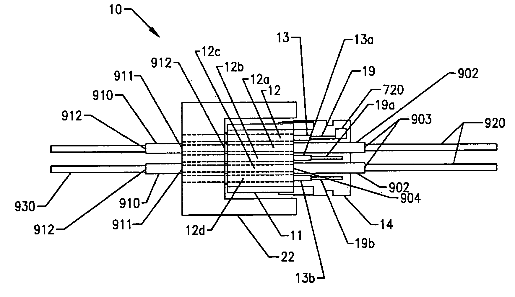
[0029]The present invention pertains to electrical connectors, and in particular, includes an extruded metallic electrical connector assembly having an extruded metallic housing with channels that do not require an insulating layer and / or an IPCB.

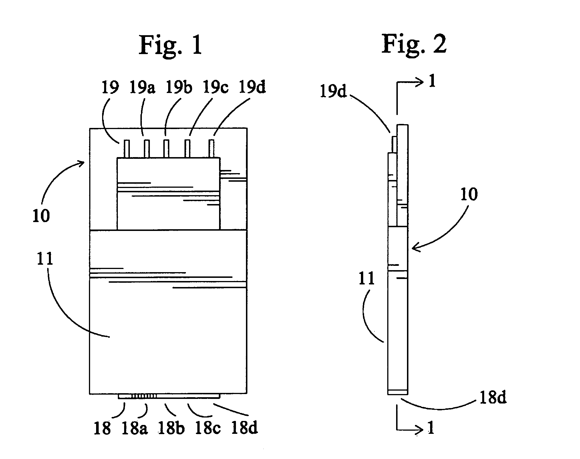
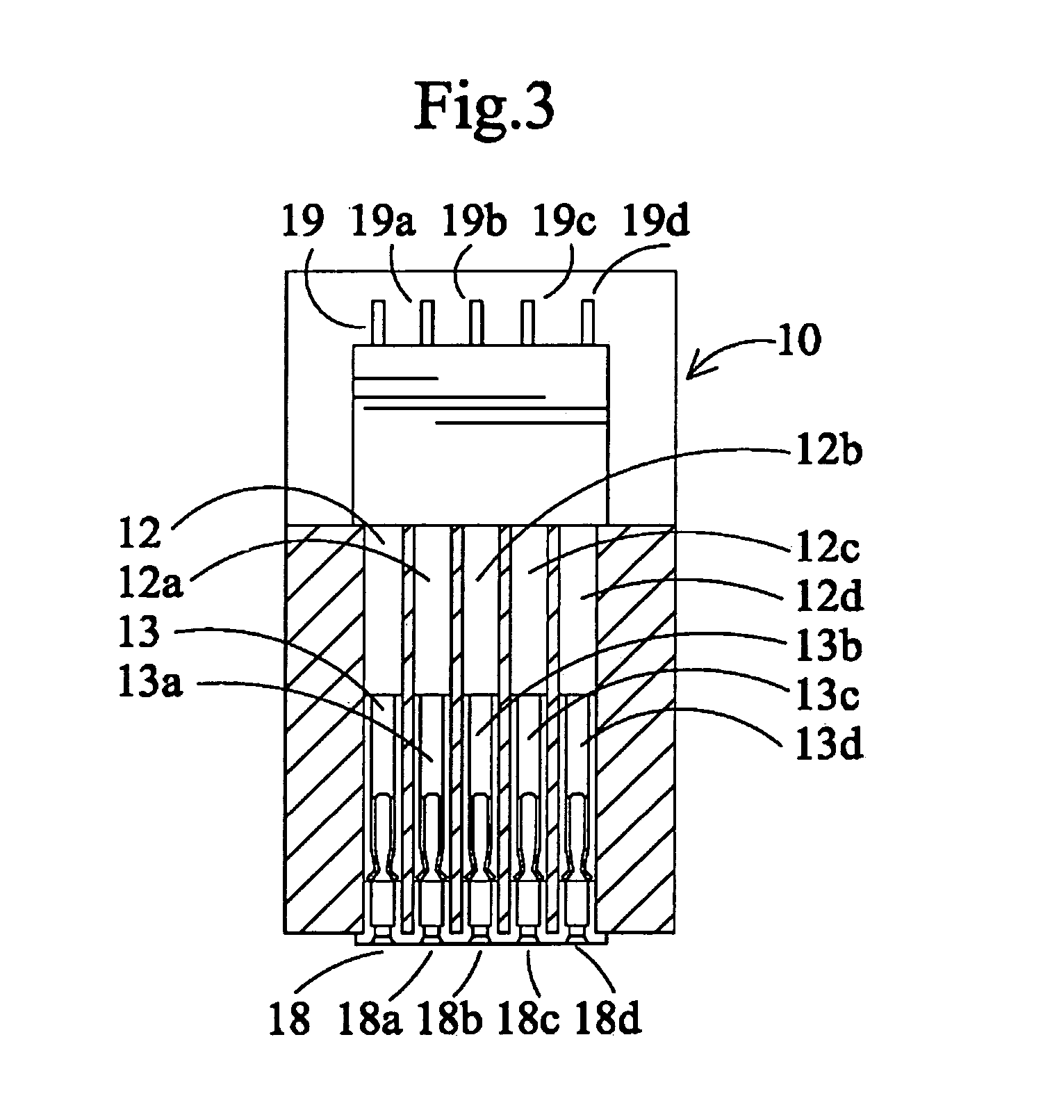
[0030]As shown in the Figures, the extruded electrical connector assembly 10 (FIG. 1) provides a four-sided metal enclosure along the length of individual contacts, for high-density low-inductance, resistance and good signal integrity. This means and method of shielding each individual contact along the contact's length by the connector housing 11 (FIG. 4) contiguously extruded from metal to form individual channels 12, 12a, 12b, 12c and 12d (FIG. 3) to house each contact providing multiple cavities. As shown in FIG. 7, the connector assembly is attached to a motherboard, thereby eliminating the need for an IPCB as part of the embodiment.

[0031]In an example embodiment, the contacts are on centers of 2 mm or less. In an example embodiment, t...


PUM


Abstract

An extruded metal connector that does not require an insulating layer in the channels is disclosed. Further an extruded metal connector that does not require and IPCB is also disclosed. The connector includes a metallic extruded housing having one or more connector channels formed therein during extrusion. The one or more connector channels have first and second ends and channel walls. The connector also includes a singular or plurality of pin guides each with a central aperture and each operatively coupled to a corresponding channel. An intermediate printed circuit board (IPCB) or other such member having one or more spaced apart first electrical contact pins serves to hold the connector pins within the connector channels and away from the channel walls by the IPCB at the first end of the channel. Pin guides arranged at the other ends of the channel support the ends of the contact pins opposite on the opposite end so that the pins remain in the center of each channel and away from the channel walls when no IPCB is used.

Description

CROSS-REFERENCE TO RELATED PATENTS AND PATENT APPLICATIONS[0001]This application is a continuation-in-part of U.S. patent application Ser. No. 10 / 321,744, entitled “Hybrid connector system and method,” which patent application is incorporated by reference herein, and which patent application has a common inventor, and which patent application is a continuation-in-part of U.S. patent application Ser. No. 10 / 040,657, entitled “Electrical connector system and method,” which patent application is incorporated by reference herein, and which patent application has a common inventor. This patent application is also related to U.S. Pat. No. 6,478,625, issued on Nov. 12, 2002, entitled “Electrical-optical hybrid connector,” which patent is incorporated by reference herein, and which patent has a common inventor. The present application is also related to U.S. Pat. No. 6,283,792 B1, issued on Sep. 4, 2001, and entitled “Extruded metallic electrical connector assembly and method of producing s...

Claims


Application Information

Patent Timeline
Patent Type & Authority Patents(United States)
IPC IPC(8): H01R11/20G02B6/38H01R13/658
CPCG02B6/3817H01R12/778H01R13/005
Inventor TOLMIE, BERNARD R
Owner TOLMIE BERNARD R
Why Eureka
Try Eureka