
Measuring apparatus for total knee replacement operation

a technology for measuring equipment and knee replacement, which is applied in the field of measuring equipment for total knee replacement operation, can solve the problems of inability to measure the gap and ligament balance with patella eversion, and achieve the effect of improving the accuracy of the measuremen

Active Publication Date: 2007-01-02
ZIMMER KK
View PDF6 Cites 422 Cited by
  • Summary
  • Abstract
  • Description
  • Claims
  • Application Information

AI Technical Summary

Benefits of technology

"The present invention provides an apparatus for measuring the gap and ligament balance in a total knee replacement operation. The apparatus includes a base, first and second engaging members, a moving body, and a driving member. The first and second engaging members are selectively moved between a direction where they are moved towards each other and a direction where they are moved away from each other. The driving member moves the moving body with respect to the base, and an locking member locks the movement of the driving member. The apparatus can be used without any substantial patella eversion, which means that the measurement is done under an intrinsic condition of the knee, and without any adverse effect caused by the measurement. The apparatus provides a simple and effective solution for measuring the joint gap and ligament balance in a total knee replacement operation."

Problems solved by technology

Such a measurement of the gap and ligament balance with the patella eversion is not desirable from the view point that a measurement during operation is done under a condition of the knee, which is quite different from a physiological condition of the knee after the completion of the operation.
Furthermore, the measurements at the extended condition (less than 180°) and the flexed condition (90°) are only possible, i.e., Ashby et al. does not make it possible to measure at any desired knee flexion angle.

Method used


Image

  • Measuring apparatus for total knee replacement operation
  • Measuring apparatus for total knee replacement operation
  • Measuring apparatus for total knee replacement operation

Examples


Embodiment Construction

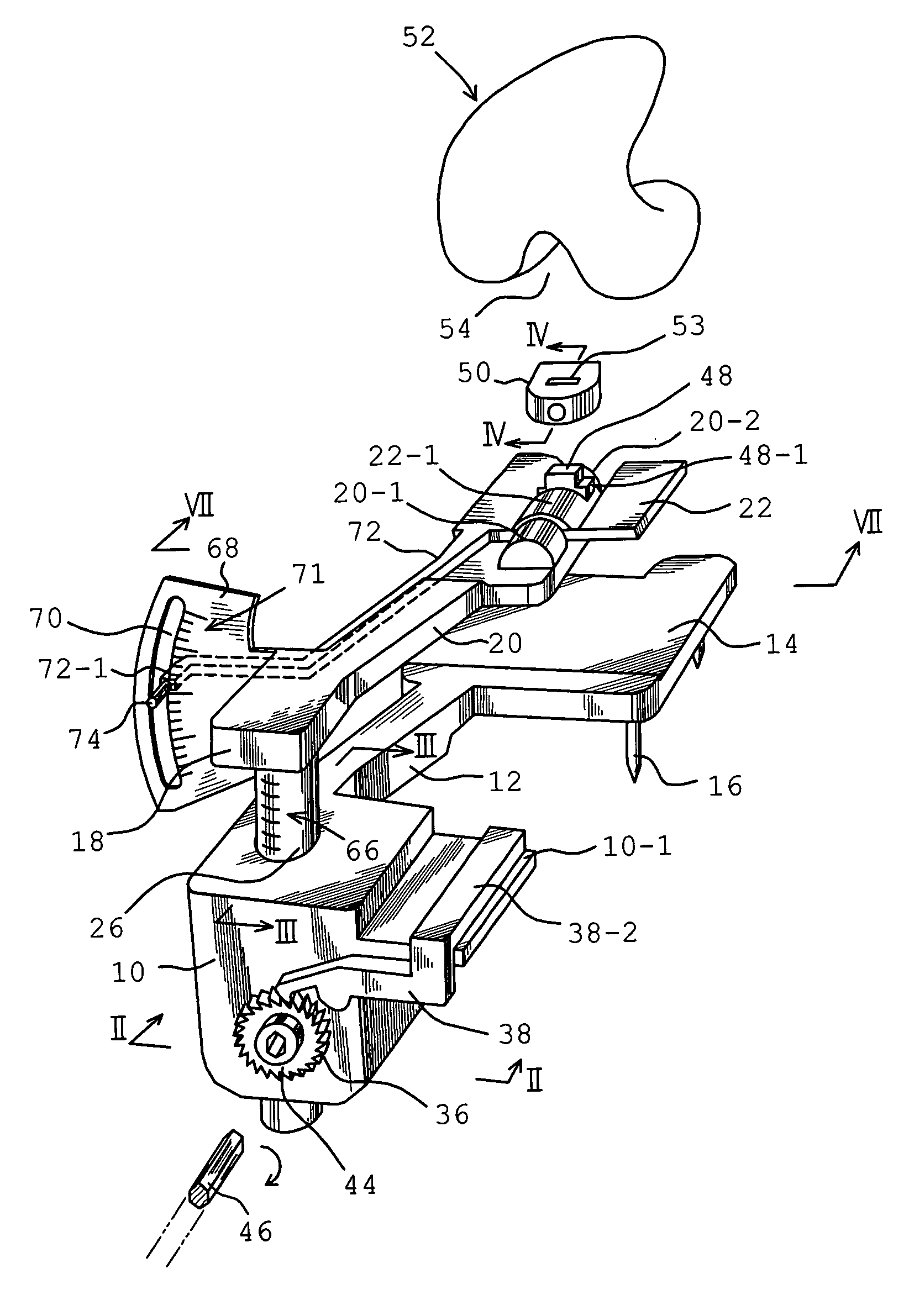
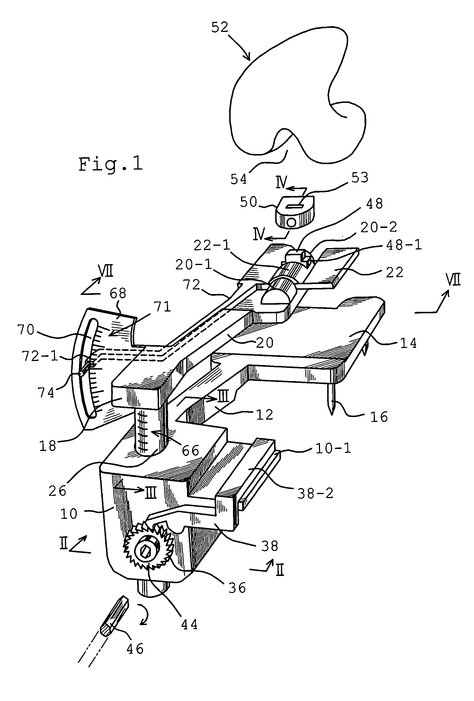
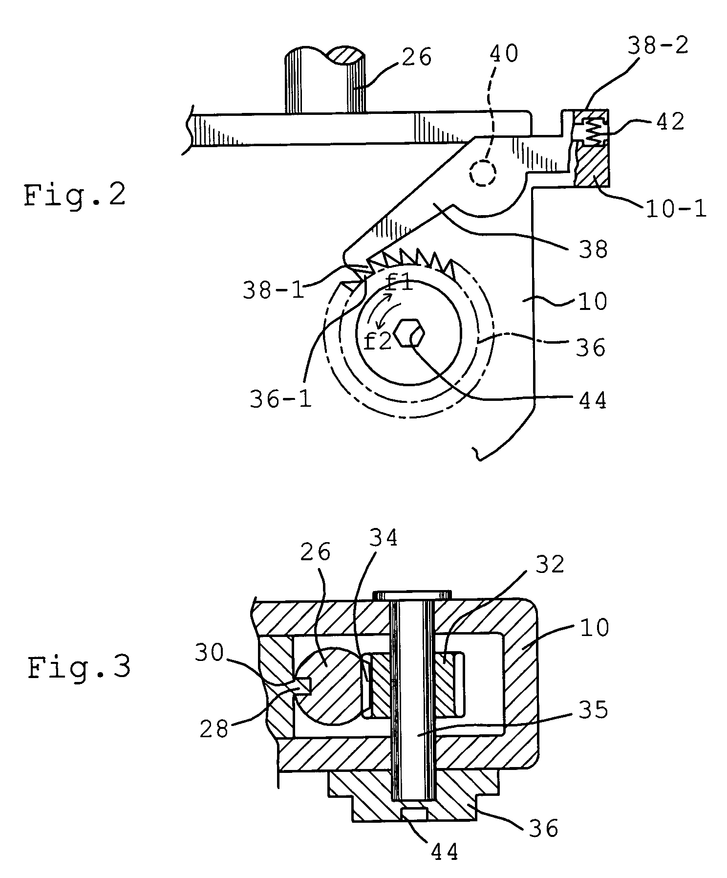
[0049]Now, an embodiment of a measuring apparatus for according to the present invention for an apparatus for measuring a joint gap and a ligament balance during the execution of a total knee replacement and arthroplasty operation will be explained with reference to attached drawings. In FIG. 1, a reference numeral 10 denotes a base having an upper part, from which an arm 12 is extended in a cantilever fashion. The arm 12 is, at its free end, integrally formed with an engaging plate 14. The engaging plate 14 is, at its lower surface, formed with fixing nails 16 of a desired number and extending downwardly. The nails 16 are for a fixation of the engaging plate 14 to an osteotomized surface at a tibial proximal end, as will be explained later in more detail with reference to FIGS. 7 and 8. In FIG. 1, the shown measuring apparatus is for an installation to a left-handed knee joint. The important feature of the present invention is that the engaging plate 14 on the tibial osteotomized s...


PUM


Abstract

An apparatus in a total knee replacement and arthroplasty operation for measuring a joint gap and ligament balance between a osteotomized surface at a femoral distal end and a osteotomized surface at a tibial proximal end. The apparatus is provided with a base 10, from which an engaging plate 14 extends by way of an arm, so that the engaging plate 14 contacts with the osteotomized surface at the tibial proximal end. A moving body 18 is vertically movably connected to the base 10, from which moving body 18 an arm 20 extends, to which arm a supporting plate 22 is rotatably mounted about a central axis. The supporting plate 22 has, at its top surface, a projected portion 48. to which an auxiliary guiding piece 50 is connected under a snap like fitted manner. A femoral component 52 is mounted, at its groove portion 54, to the osteotomized surface at the femoral distal end. The engaging plate 14 as well as the supporting plate 22 are under an offset arrangement with respect to the base and moving body, respectively.

Description

BACKGROUND OF THE FIELD OF THE INVENTION[0001]1. Field of the Invention[0002]The present invention relates to an apparatus used for a surgical operation, in particular, to an apparatus used in a total knee replacement (TKR) operation and a total knee arthroplasty (TKA) operation for measuring a gap (joint gap) between osteotomized surfaces at a femoral distal end and a tibial proximal end as well as an inclination between the osteotomized surfaces (ligament balance).[0003]2. Description of Related Art[0004]In the knee replacement and arthroplasty operation, a replacement to knee prosthesis (tibiofemoral (T-F) joint) is done. Known in a prior art is a knee prosthesis, which includes a femoral component made of a metal material and fixed to an osteotomized surface at a femoral distal end, a tibial plate made of a metal material and fixed to an osteotomized surface at a tibial proximal end, and a surface component made of a plastic material such as a polyethylene and arranged between t...

Claims


Application Information

Patent Timeline
Patent Type & Authority Patents(United States)
IPC IPC(8): A61B17/56A61B5/107A61B17/02A61B17/15A61B19/00A61F2/46
CPCA61B17/0206A61B17/025A61B19/46A61B17/154A61B2019/467A61B2017/0268A61B2019/461A61B2019/464A61B2090/064A61B2090/067A61B90/06A61B2090/061
Inventor MURATSU, HIROTSUGU
Owner ZIMMER KK
Learn More