Light emission display arrangements

a technology of display and light emission, applied in the direction of discharge tube main electrodes, identification means, instruments, etc., can solve the problems of many devices of this type not producing much light individually, affecting the operation of the device, and the electroluminescent materials used may degrade at different rates at different temperatures, so as to improve the cooling arrangement of such displays and improve the addressable display

Inactive Publication Date: 2007-01-02
BARCO NV
View PDF17 Cites 97 Cited by
  • Summary
  • Abstract
  • Description
  • Claims
  • Application Information

AI Technical Summary

Benefits of technology

[0009]It is an object of the present invention to provide improved addressable displays and in particular to provide improved cooling arrangements for such displays, especially tiled or segmented displays.
[0010]It is also an object of the present invention to provide improved addressable displays and in particular to provide improved cooling arrangements for such displays suitable for use where the display must be sealed, e.g. against dust or water, or out of doors where they can be subject to moisture.
[0011]It is an object of the present invention to provide improved displays and in particular to provide improved cooling arrangements for such displays, especially tiled or segmented displays.
[0012]It is also an object of the present invention to improve the compactness of displays having cooling arrangements.
[0019]The present invention also provides a tiled panel display formed from a plurality of display panels according to the invention, said plurality of display panels preferably being juxtaposed and configured to form a unified tiled display. The inlets and / or outlets of the cooling channels need not be linked between said plurality of display panels forming said tiled display. Each cooling channel may discharge the fluid separately, for instance. Alternatively, the cooling may be provided by forcing a cooling fluid through several or all of the display tiles, some of which are connected in series to form a cooling circuit. In some cases, e.g. if cooling is very critical, it is advantageous to only have short cooling channels. In this way, the temperature drop between the beginning and the end of the cooling channel is reduced.

Problems solved by technology

Many devices of this type do not, however, produce much light individually and need to be grouped into arrays in order to be useful for many applications.
The collective heat generated by such arrays may prove harmful to the devices forming the array and the ability to dissipate it will dictate the density of devices in the array and their durability.
This problem is particularly acute in tiled display apparatus, which may be assembled by juxtaposition of a plurality of arrays and provide little scope for peripheral heat dissipation due to their abutting each other along their side edges.
Further, electroluminescent materials used may degrade at different rates at different temperatures.
For example, aging may result in lower luminosity and / or colour shifts and therefore to variations in display quality across a large display area.
Where displays have to be sealed against water or dust this sealing can increase the difficulty of extracting heat.
This makes it less than ideal for use in a tiled array, where adjoining tiles would all be dissipating heat around their abutting edges.
Also the display has a considerable thickness or depth and weight caused by the plurality of heat sinks which need to contain significant amounts of metal to be effective.
An arrangement such as the one proposed in U.S. Pat. No. 6,255,786 may prove bulky for use in a tiled array, requiring a rear mounted fan for each tile.
Cooling air being blown onto the rear of the heat sink may be deflected sideways off the heat sink and interfere with the equivalent arrangement of adjacent arrays.

Method used


Image

  • Light emission display arrangements
  • Light emission display arrangements
  • Light emission display arrangements

Examples


Embodiment Construction

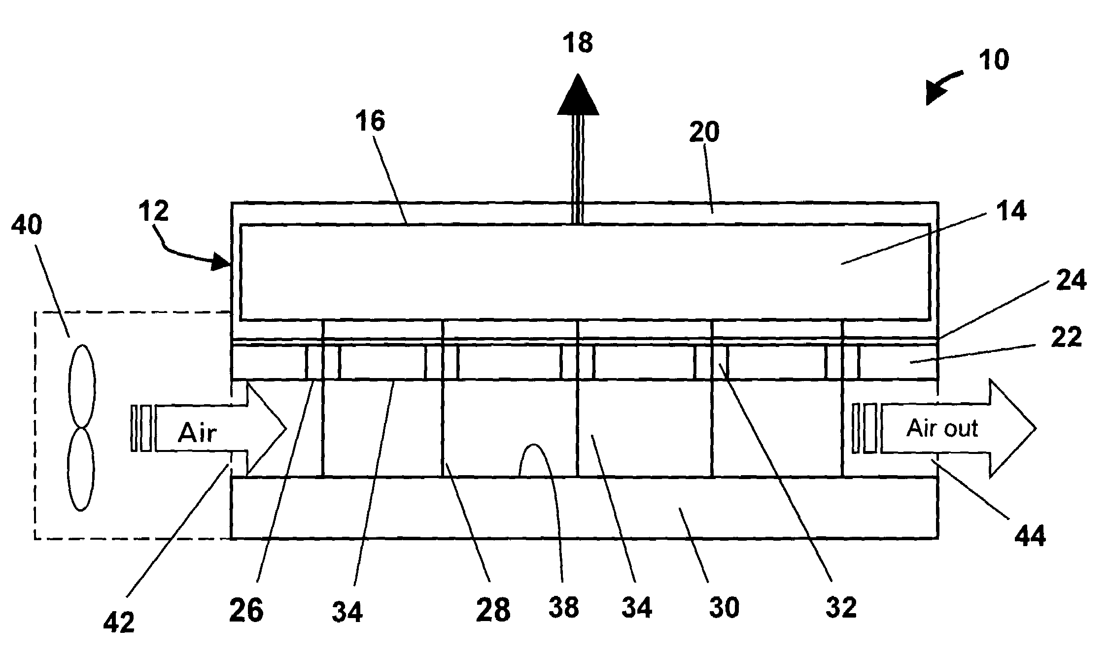
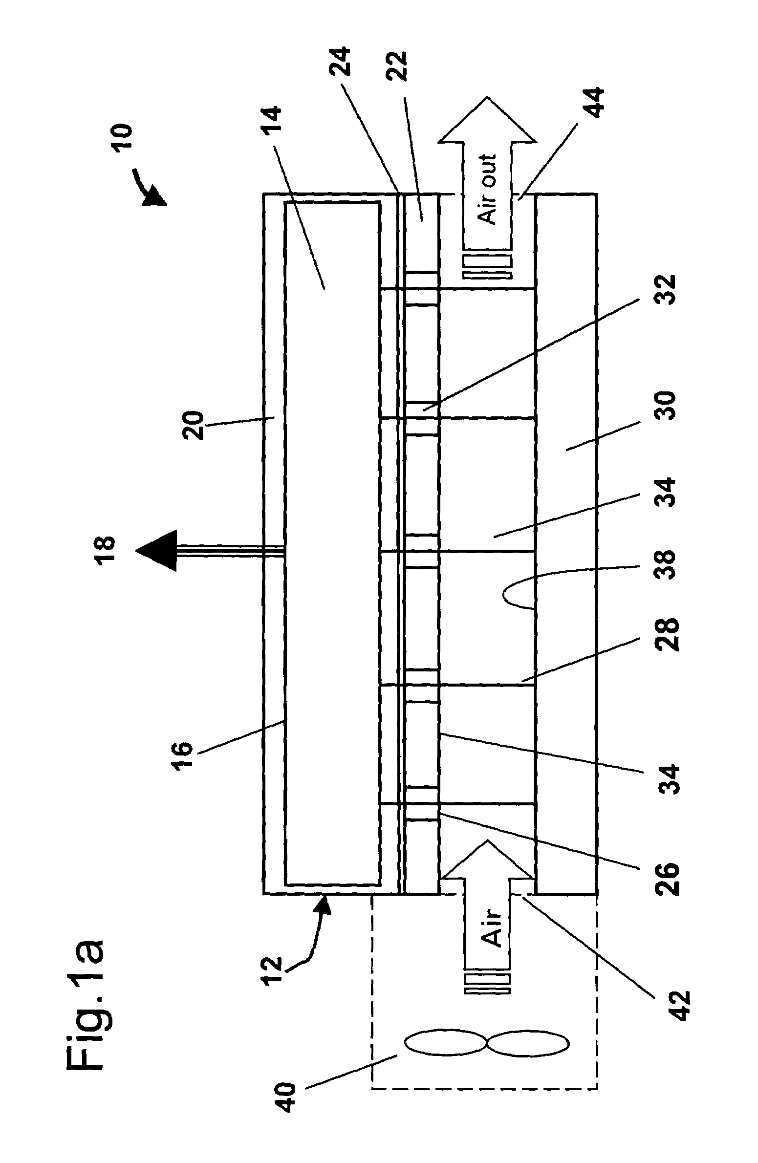
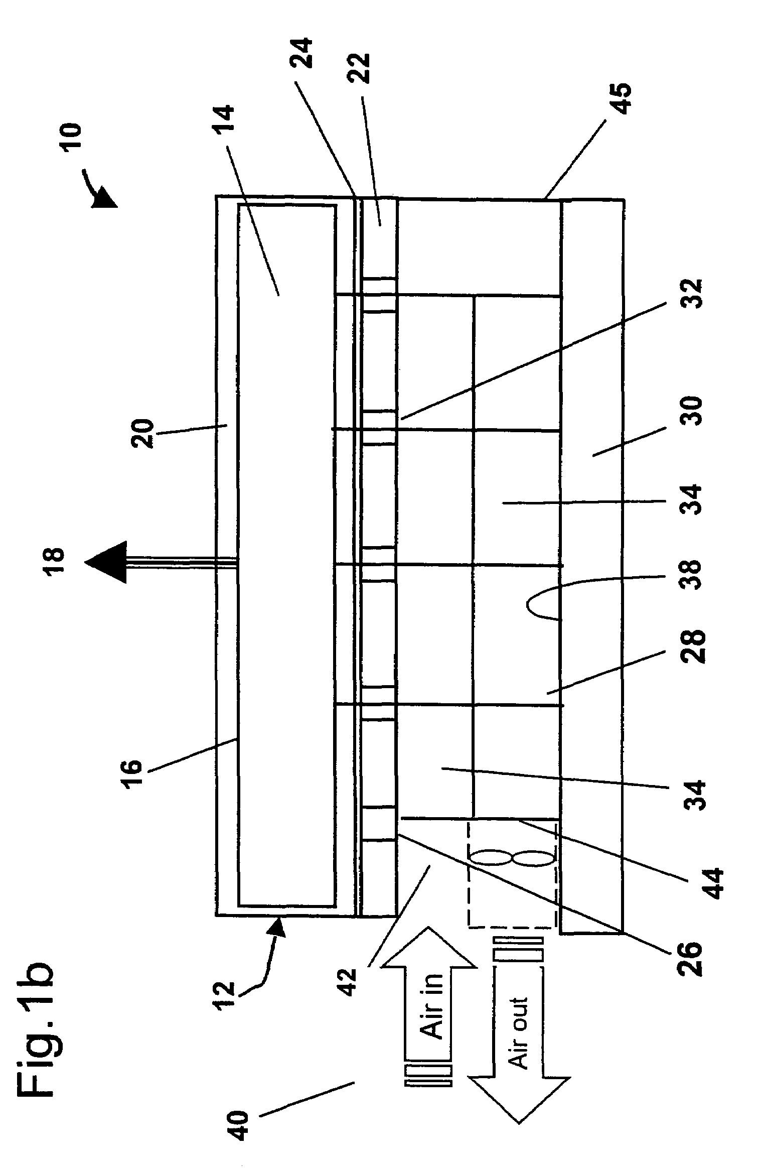
[0045]The present invention will now be described by way of example only, with reference to certain embodiments and with reference to the above mentioned drawings. The skilled person will appreciate that many alternative arrangements are possible while still remaining within the scope of the attached claims. The invention will be described with reference to flat panel displays. It is understood that a flat panel display does not have to be exactly flat but includes shaped or bent panels. A flat panel display differs from display such as a cathode ray tube in that it comprises a matrix or array of “cells” or “pixels” each producing or controlling light over a small area. There is a relationship between the pixel of an image to be displayed and a cell of the display. Usually this is a one-to-one relationship. Each cell may be addressed and driven separately. It is not considered a limitation on the present invention whether the flat panel displays are active or passive matrix devices....


PUM


Abstract

The present invention provides arrangements for electroluminescent displays 10 comprising a packaged semiconductor light emitting element 12 that has a light emitting display side 16. A heat sink 22 is disposed in the region of a rear side of the light-emitting element 12 opposite to the display side. Electrical connections 28 from the light emitting element 12 pass through said heat sink 22. Drive circuitry 30 for the light emitting element 12 is connected thereto by the electrical connections 28 and spaced apart from the heat sink 22 in such a manner that at least one cooling channel 34 is defined between the heat sink 22 and the drive circuitry 30 for the passage in use of a cooling fluid.

Description

RELATED APPLICATION[0001]This application is the nonprovisional filing of provisional application No. 60 / 417,515, filed Oct. 10, 2002.FIELD OF THE INVENTION[0002]The present invention relates to light emission from displays, e.g. flat panel displays and in particular to methods and apparatus for cooling a flat panel display, especially a large size segmented or tiled display, e.g. an LED or OLED display. The displays are preferably suitable for display of varying digital or analog information, e.g. video films, television or camera pictures. The displays may be for use indoors or outdoors.BACKGROUND TO THE INVENTION[0003]It is known to provide an electroluminescent element, arranged for example in the form of a lighting unit or a display, especially as a flat panel display. Flat panel displays are described in “Display interfaces”, R. L. Myers, Wiley, 2002. The electroluminescent element of a flat panel display may comprise one or more devices such as light emitting diodes (LED's), ...

Claims


Application Information

Patent Timeline
Patent Type & Authority Patents(United States)
IPC IPC(8): H01J7/26H01L51/50G09F9/00G09F9/30G09F9/33G09G3/20G12B15/00H01L51/52H05B33/14H05K7/20
CPCG09F9/33G09F9/3026H01L51/529H01L27/3293H10K59/18H10K50/87
Inventor THIELEMANS, ROBBIEOOGHE, KOENDE KEUKELEIRE, STEVENDEVOS, BRUNOVELDEMAN, STEVEDECLERCK, TOMMEERSMAN, KARIMVANLUCHENE, KRISTOFVAN HILLE, HERBERT
Owner BARCO NV
Why Eureka
Try Eureka