
System for testing flat panel display devices

a display device and flat panel technology, applied in the field of display device testing, can solve the problems of high precision requirements, increase in display panel size, and increase in the production of flat panel display devices, etc., and achieve the effect of facilitating subsequent troubleshooting of defective display devices

Inactive Publication Date: 2007-01-02
HANNSPREE INC
View PDF2 Cites 5 Cited by
  • Summary
  • Abstract
  • Description
  • Claims
  • Application Information

AI Technical Summary

Benefits of technology

[0007]Therefore, the object of the present invention is to provide a system for testing flat panel display devices that eliminates the need to lift the display devices during testing and that can facilitate subsequent troubleshooting of defective display devices.

Problems solved by technology

However, with the increase in the size of display panels, the production of flat panel display devices, such as LCD televisions, plasma televisions, etc., has also become quite complex in view of high precision requirements in electrical connections between a display panel and associated electronic components.
It is noted that the act of lifting display devices during testing is not only labor intensive, but also slows down the production flow and increases the production cost.

Method used


Image

  • System for testing flat panel display devices
  • System for testing flat panel display devices
  • System for testing flat panel display devices

Examples


Embodiment Construction

[0015]Before the present invention is described in greater detail with reference to the accompanying preferred embodiments, it should be noted herein that like elements are denoted by the same reference numerals throughout the disclosure.

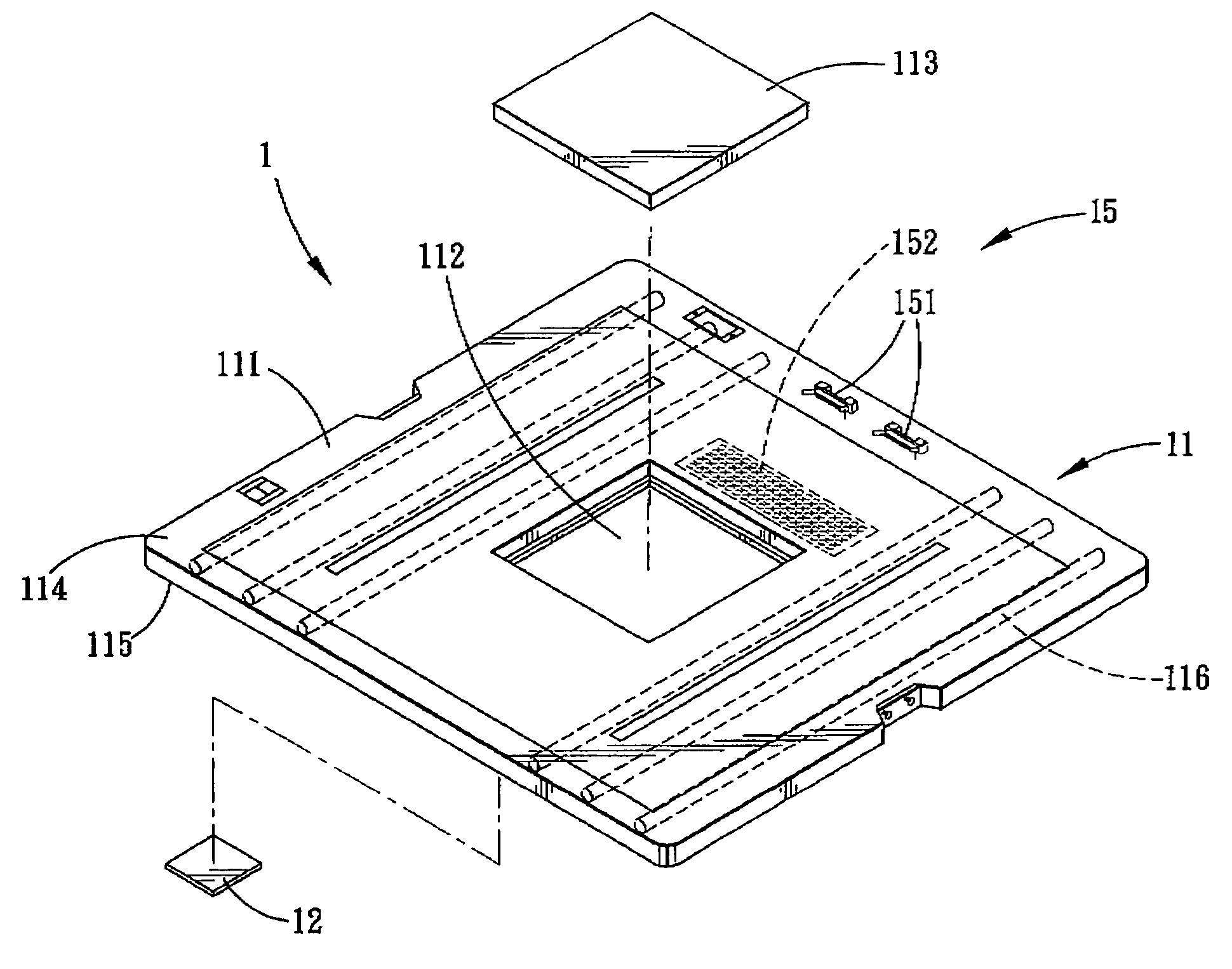
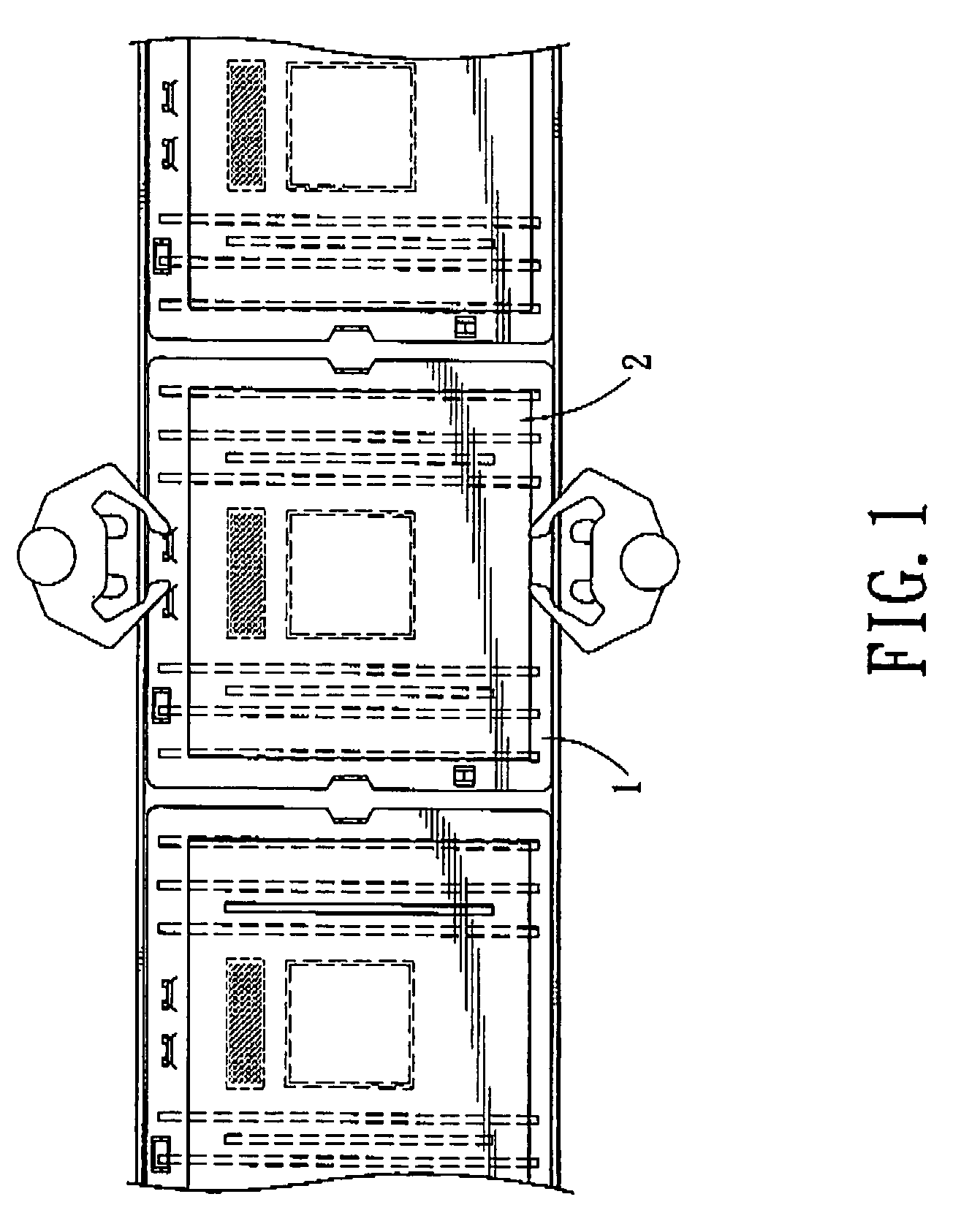
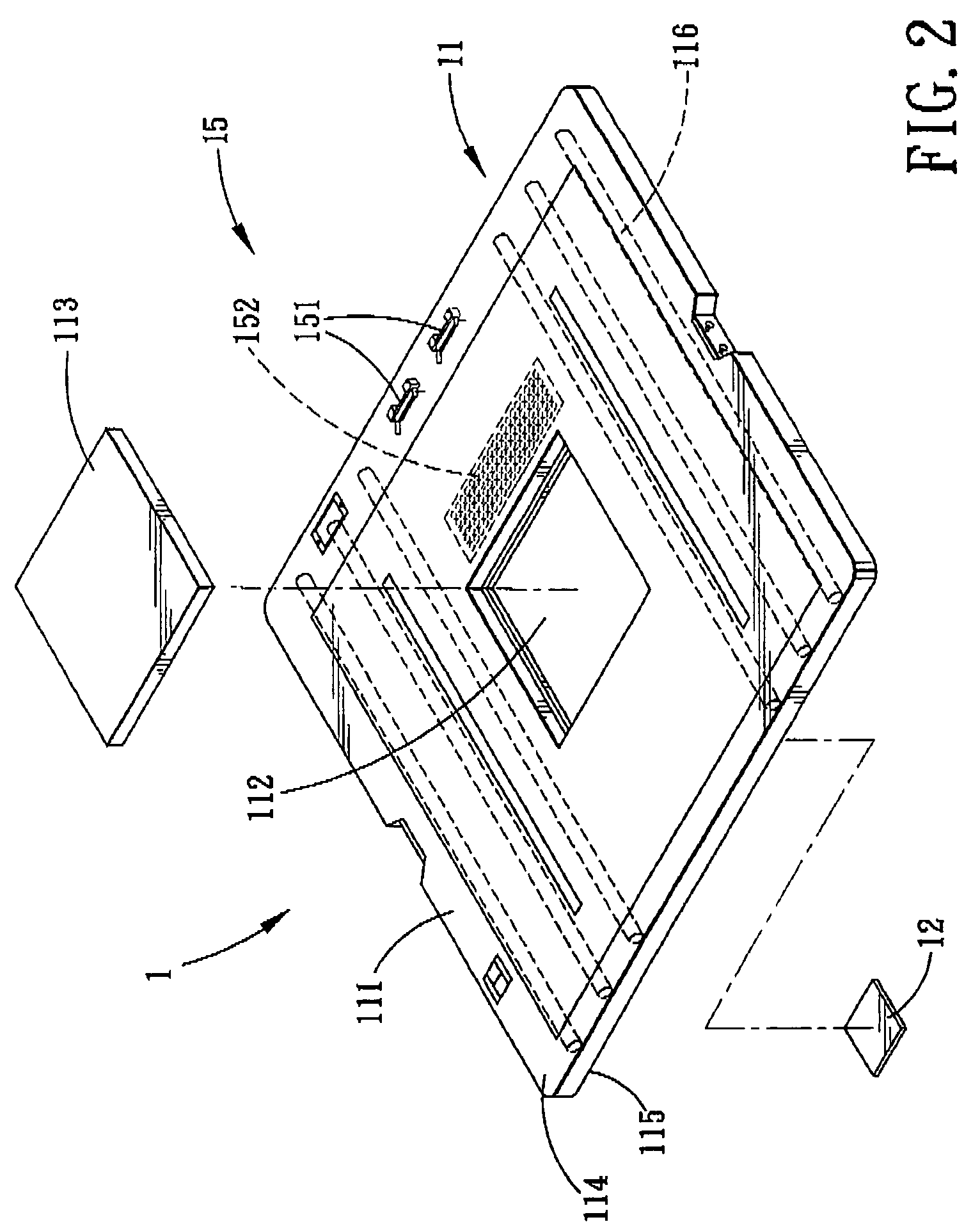
[0016]Referring to FIG. 1, the first preferred embodiment of a system 1 according to the present invention is shown to be adapted for testing large size display devices 2, such as LCD televisions or plasma televisions. Referring to FIGS. 2 and 3, the system 1 is shown to comprise a support plate 11, an electrical connector set 15, and a light-directing component 12.

[0017]The support plate 11, which is a component assembly support plate used in component assembly operations, includes a plate body 111 having upper and lower surfaces 114, 115, and a through hole 112 formed through the upper and lower surfaces 114, 115. In use, the support plate 11 is adapted to support the display device 2 thereon such that a screen 21 of the display device 2 faces the...


PUM


Abstract

A system for testing a flat panel display device includes a support plate and an electrical connector set. The support plate includes a plate body having a through hole, and is adapted to support the display device thereon such that a screen of the display device faces an upper surface of the plate body. The electrical connector set is mounted on the support plate, and is adapted to connect electrically with the display device on the support plate so as to enable activation of the display device to radiate light from the screen of the display device through the through hole. One of a light-directing component and an image-capturing unit is disposed under and is spaced apart from the support plate, to receive the light from the display device that passes through the through hole.

Description

CROSS-REFERENCE TO RELATED APPLICATION[0001]This application claims priority of Taiwanese application no. 094220128, filed on Nov. 21, 2005.BACKGROUND OF THE INVENTION[0002]1. Field of the Invention[0003]The invention relates to testing of display devices, more particularly to a system for testing flat panel display devices.[0004]2. Description of the Related Art[0005]As a result of ongoing advancements in display device technology, it is now possible to fabricate display devices for household use that have 40-inch display panels. However, with the increase in the size of display panels, the production of flat panel display devices, such as LCD televisions, plasma televisions, etc., has also become quite complex in view of high precision requirements in electrical connections between a display panel and associated electronic components. With the large size and heavy weight of display devices, at least two operators are required to accomplish some manual assembly tasks.[0006]During f...

Claims


Application Information

Patent Timeline
Patent Type & Authority Patents(United States)
IPC IPC(8): G01R31/00
CPCG09G3/006
Inventor KUO, SHIH-CHUNGHUANG, MAKOTO
Owner HANNSPREE INC
Learn More