Active noise control system

Active Publication Date: 2007-01-02
PANASONIC CORP
View PDF12 Cites 8 Cited by
  • Summary
  • Abstract
  • Description
  • Claims
  • Application Information

AI Technical Summary

Benefits of technology

[0017]A purpose of the present invention is to implement an active noise control system for obtaining a sufficient noise reduction effect, even in an apparatus having ducts that expel or absorb fluid in complicated forms, without increasing the size of the apparatus having the noise source.
[0018]An active noise control system according to the present invention is provided with a noise detector for detecting noise in a duct where a fluid flows and an error detector provided in a downstream side of the noise to detect an error sound. In addition, a control sound source is installed in the vicinity of the error detector and a control sound having approximately the same sound pressure as of and an opposite phase to the noise within the duct is radiated. At this time, a noise signal of the noise detector and an error signal of the error detector are inputted to an arithmetic circuit and a transfer function is set so that the error signal becomes small. Furthermore, a fluid within the duct is rectified or made into a laminar flow by providing a rectifying part in the upstream s

Problems solved by technology

In addition, noise has been attenuated by installing a sound absorbing material.
In such environments, however, it has been difficult to carry out above described measures.
Since noise in residential spaces is increased in the above manner, an amelioration of this situation is required.
In this case, exhaust noise or induction noise for cooling is often annoying.
There is a problem, however, that a large volume duct is required for reducing noise of a frequency of 1 kHz or less by means of these methods.
In

Method used


Image

  • Active noise control system
  • Active noise control system
  • Active noise control system

Examples


first embodiment

[0044](First Embodiment)

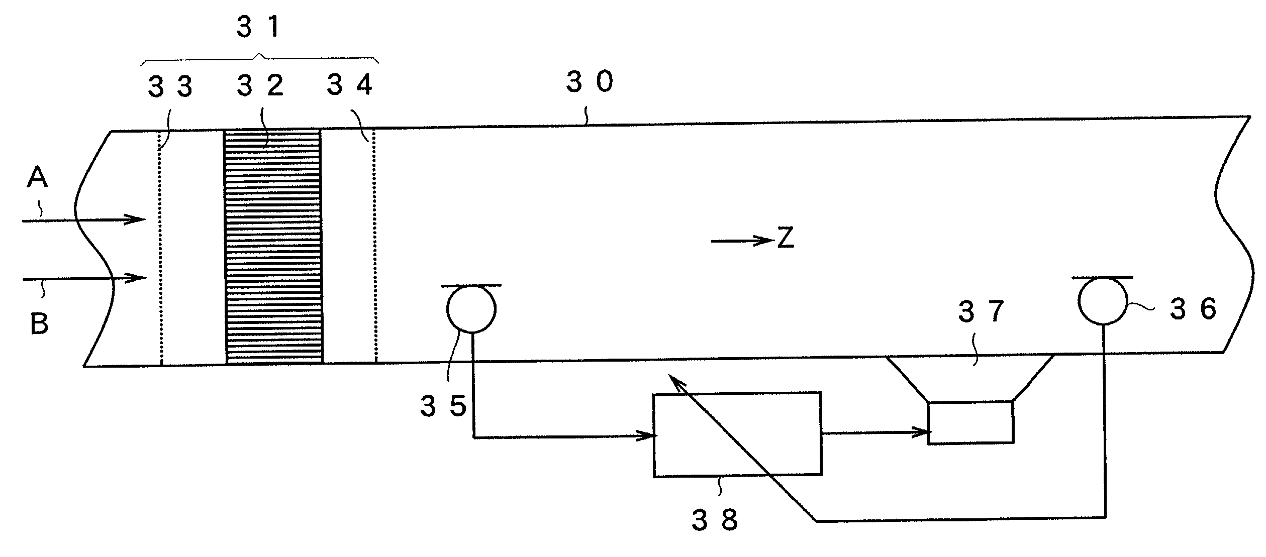
[0045]The configuration of an active noise control system according to first embodiment of the present invention is described with reference to FIG. 7. A duct 30 is a duct for conveying (sending) a fluid A to the outside of the system. This duct 30 is different from a straight duct as shown in FIGS. 1, 2, 4 and 5 and a part of the duct having a complicated fluid path is shown and only a straight portion that allows the fluid A to flow in the direction of Z is represented. The duct of the present embodiment may, of course, be a duct of a structure such as in the prior arts. A noise B is propagated together with the fluid A in the direction of Z from the upstream of the duct 30. In the following description, the part shown in the figure is referred to as a duct 30.

[0046]The fluid A is air for air conditioning or for cooling and is supplied by a fan of a air blower which is not shown. Due to the rotation of this fan, rotational factors, disturbance factors, swir...

second embodiment

[0066](Second Embodiment)

[0067]Next, an active noise control system according to the second embodiment of the present invention is described in detail in reference to FIGS. 15 to 21. A configuration diagram of the entirety of the active noise control system according to the present second embodiment is shown in FIGS. 15 and 16. The coherence between the noise signal of the noise detection microphone and the error signal of the error detection microphone gained by the active noise control system of the present embodiment is shown in FIGS. 17 to 21.

[0068]As shown by the arrow in FIG. 15, a fluid A flows in the direction of Z and a noise B is also propagated in the direction of Z. A plurality of noise detection microphones 45a, 45b . . . 45n is attached to a duct 40 and a control sound source 47 and error detection microphones 46a, 46b . . . 46h are attached to this duct 40 downstream from the plurality of noise detection microphones. The number of noise detection microphones and the n...


PUM


Abstract

A first rectifying net, a rectifying grid and a second rectifying net are attached, as a rectifying part upstream of a duct through which air for cooling flows. A noise detection microphone detects noise within the duct. An error detection microphone is placed in the downstream side of the noise to detect error noise. An arithmetic circuit inputs a noise signal of the noise detection microphone, carries out an arithmetic of a transfer function so that an output signal of the error detection microphone becomes minimum, and outputs a control signal to a control sound source. The control sound source radiates a control sound having approximately the same sound pressure as and an opposite phase of the noise within the duct. Thus, the coherence between the noise in the upstream and downstream parts increases, thereby enhancing a sound-muffling effect.

Description

BACKGROUND OF THE INVENTION[0001]1. Field of the Invention[0002]The present invention relates to an active noise control system for reducing noise generated in a duct for a fluid.[0003]2. Description of the Related Art[0004]Together with the increased density of today's residential and labor environments, cases in which noise sources such as air conditioning equipment and office equipment and residential spaces are in proximity to each other have increased. Up to the present, the muffling or the cut off of noise has been effectuated by making the distance between noise sources and people great. In addition, noise has been attenuated by installing a sound absorbing material. In such environments, however, it has been difficult to carry out above described measures.[0005]Since noise in residential spaces is increased in the above manner, an amelioration of this situation is required. In addition, office equipment is provided with cooling fans and ducts for exhaust or for induction in ...

Claims


Application Information

Patent Timeline
IPC IPC(8): H03B29/00F16L55/04G10K11/178H04R3/00
CPCG10K11/1788G10K11/1784G10K11/17815G10K11/17823G10K11/17825G10K11/17881
Inventor KAKUHARI, ISAOTERAI, KENICHIHASHIMOTO, HIROYUKI
Owner PANASONIC CORP
Why Eureka
Try Eureka