Soundproof structure

a sound insulation structure and sound insulation technology, applied in the field of sound insulation structures, can solve the problems of insufficient sound absorption performance, heavy sound insulation structure, large element size, etc., and achieve the effects of high sound absorption rate, high sound insulation performance, and small siz

Active Publication Date: 2021-01-26
FUJIFILM CORP
View PDF25 Cites 0 Cited by
  • Summary
  • Abstract
  • Description
  • Claims
  • Application Information

AI Technical Summary

Benefits of technology

[0010]Compared with the related art, the sound insulation structures disclosed in JP1995-019154B (JP-H07-019154B) and JP1999-327563A (JP-H11-327563A) are lightweight and simple structures with high versatility, and a sufficient noise reduction effect is obtained. In particular, the sound insulation performance in a low frequency band is excellent. However, in the sound insulation structures disclosed in JP1995-019154B (JP-H07-019154B) and JP1999-327563A (JP-H11-327563A), a metal piece is used as a weight, a thin steel plate is used as a film, and the purpose is being applied to the exterior material of a building. Accordingly, there has been a problem that the sound insulation structures are heavy and large.
[0014]In order to solve the aforementioned problems of the related art, it is an object of the present invention to provide a soundproof structure that is small and has high soundproofing performance with respect to sound in a low frequency band.
[0015]More specifically, it is an object of the present invention to provide a soundproof structure capable of absorbing sound in a lower frequency band with a high sound absorption rate, in particular, absorbing sound in a low frequency band without increasing the size, in a case where the space volume used for a film type sound absorbing material having a rear air layer is limited.
[0028]According to the present invention, it is possible to provide a soundproof structure that is small and has high soundproofing performance with respect to sound in the low frequency band.
[0029]In addition, according to the present invention, it is possible to absorb sound in the lower frequency band with a high sound absorption rate in a case where the space volume used for a film type sound absorbing material having a rear air layer is limited. According to the present invention, in particular, sound in the low frequency band can be absorbed without increasing the size.
[0030]Therefore, according to the present invention, for example, it is possible to obtain a high sound absorption rate in a frequency band lower than in the related art with the same size as in the related art.

Problems solved by technology

Accordingly, there has been a problem that the sound insulation structures are heavy and large.
In addition, there is a problem that the sound absorption performance cannot be said to be sufficient in a case where neither the traveling direction of the acoustic wave nor the normal vector of the film surface is horizontal (that is, parallel).
Such an increase in the size of an element makes it difficult to use the element, for example, in a case where the space is limited, that is, in a narrow duct or a ventilation sleeve.
In this method, however, there is a problem that the absorbance is reduced even though the absorption peak can be made in the low frequency band.

Method used


Image

  • Soundproof structure
  • Soundproof structure
  • Soundproof structure

Examples


example 1

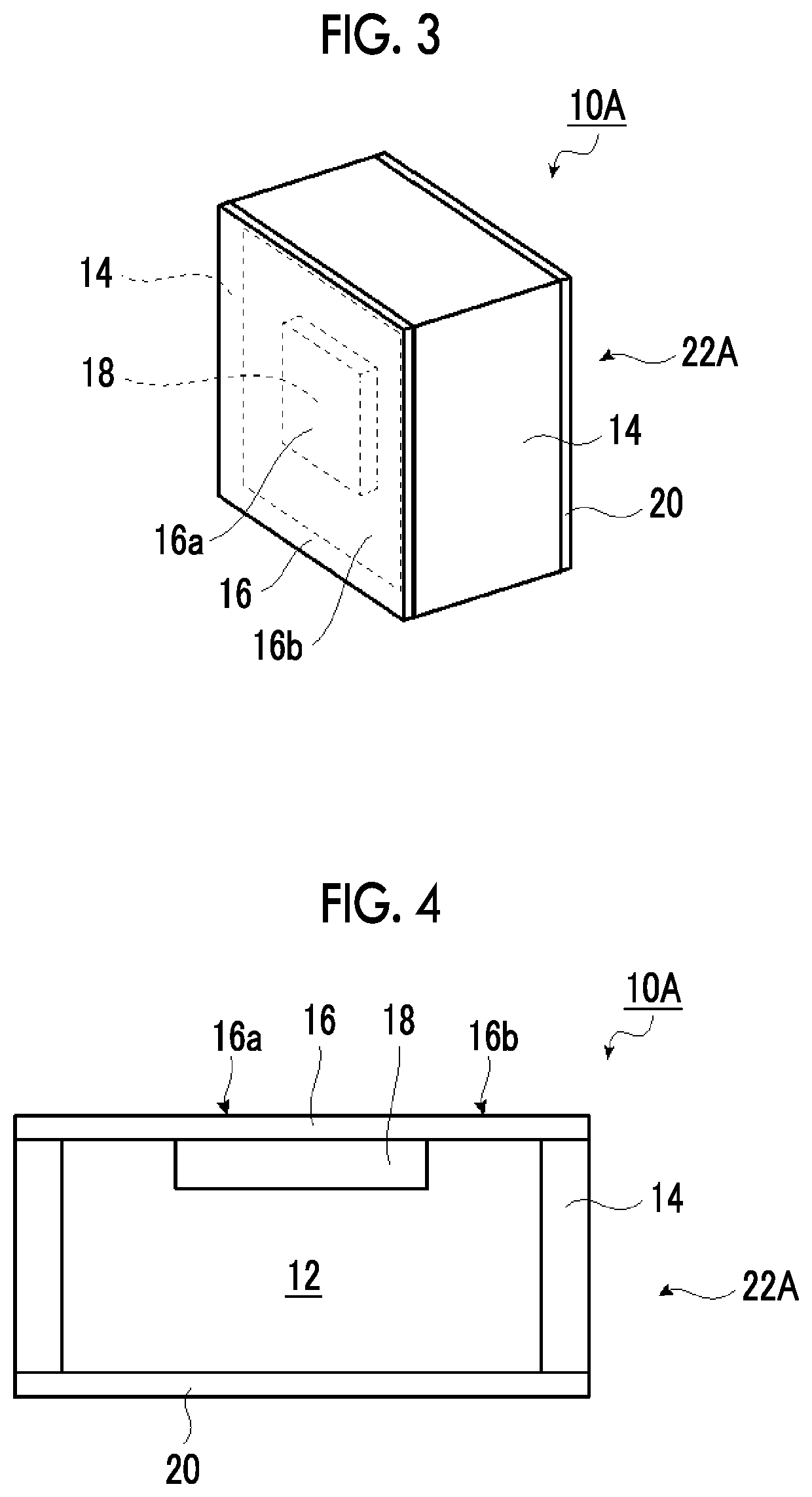
[0224]First, the soundproof structure 10A of the present invention shown in FIGS. 3 and 4 was manufactured as Example 1.

[0225]The soundproof structure 10A shown in FIGS. 3 and 4 was configured to include the soundproof cell 22A having the frame 14, which had the hole portion 12, and the vibratable film 16, which was fixed to the frame 14 so as to cover the hole portion 12.

[0226]In Example 1, a PET film (Lumirror manufactured by Toray Industries, Inc., 125 μm in thickness) was used as the film 16. An acrylic piece that had a square shape with a side of 20 mm and had a thickness of 3 mm was disposed at the center of the film 16 formed of a PET film as the protruding portion 18, and was attached to the film 16 with a tape. As the frame 14, a square tube of metal aluminum was used in which the length (rear distance) was 20 mm, the hole portion 12 was a square with an inner side of 40 mm, and the thickness of the outer periphery of the frame 14 for fixing the film 16 was 3 mm. Similarly,...

example 2

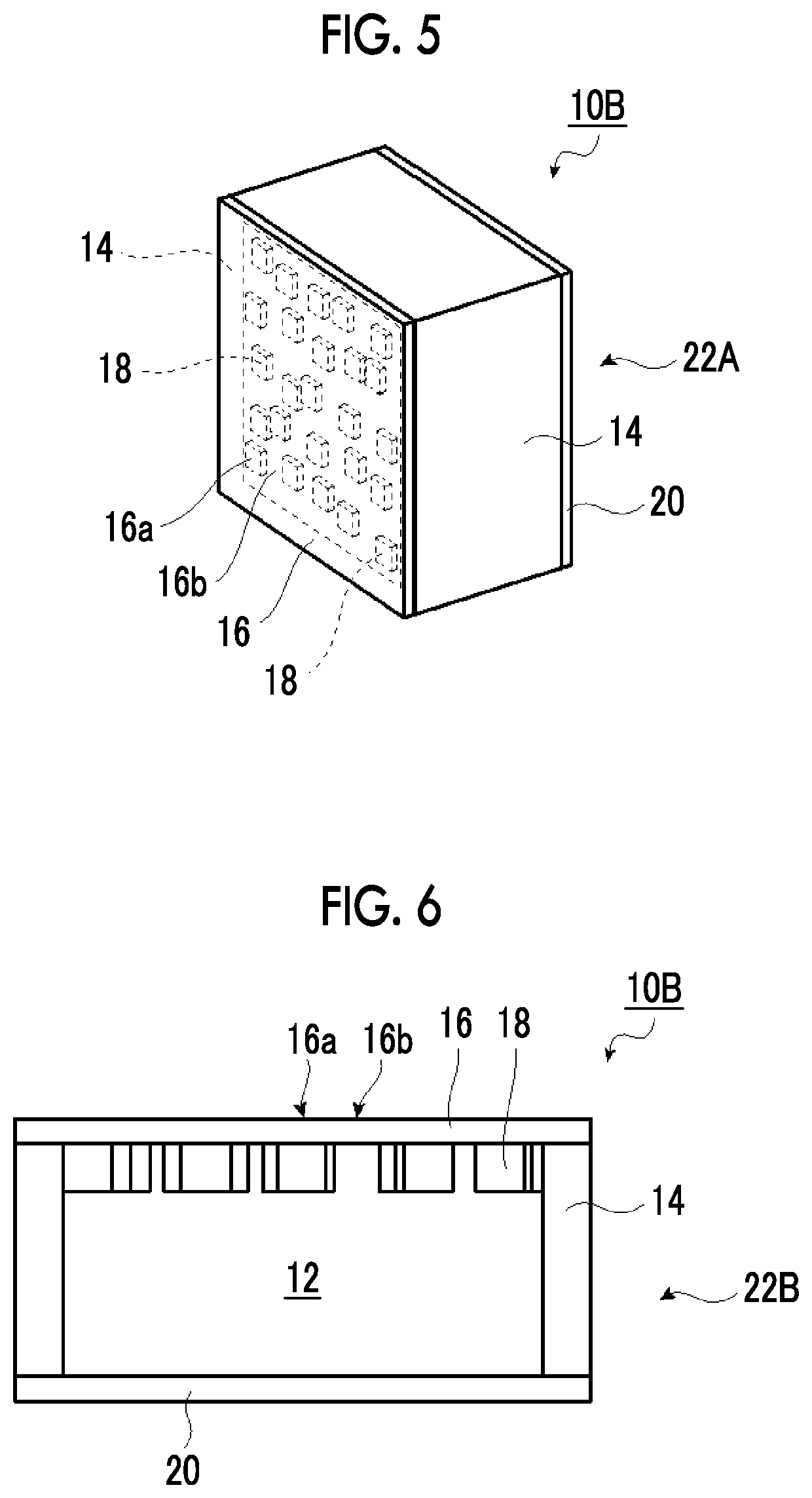
[0242]A soundproof structure, which was the same as that in Example 1 except for a PET film in which 3×3 (9) acrylic pieces (square shape having a height of 3 mm and a side of 6.7 mm) were uniformly disposed at intervals of 6.7 mm on the film 16, was manufactured.

[0243]In Example 2, ρmax / ρmin=25. The shortest line segment length Δd was 3.3 mm (3.3×10⁻³ m). The longest line segment length L was 56.6 mm (56.6×10⁻³ m).

example 3

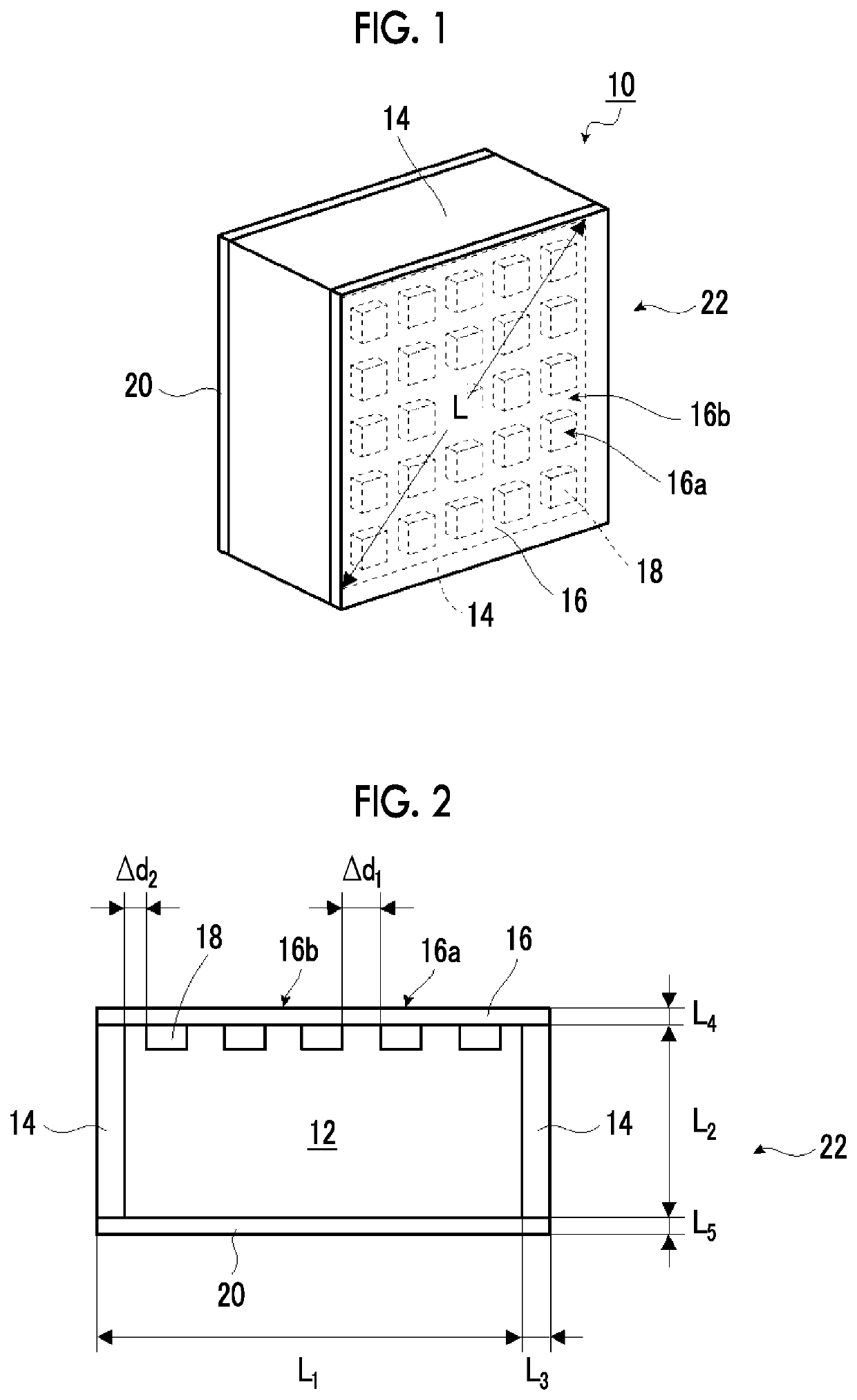
[0244]A soundproof structure 10 configured to include the soundproof cell 22 shown in FIGS. 1 and 2, which was the same as the soundproof structure in Example 1 except for a PET film in which 5×5 (25) acrylic pieces (square shape having a height of 3 mm and a side of 4 mm) were uniformly disposed at intervals of 4 mm on the film 16, was manufactured.

[0245]In Example 3, ρmax / ρmin=25. The shortest line segment length Δd was 2.0 mm (2.0×10⁻³ m). The longest line segment length L was 56.6 mm (56.6×10⁻³ m).


PUM


Abstract

There is provided a soundproof structure that is small and has high soundproofing performance with respect to sound in a low frequency band.At least one soundproof cell including a frame having a hole portion and a film fixed to the frame is provided. The film has a surface density distribution. Assuming that a shortest line segment length between high surface density regions and between the high surface density regions and end portions of the hole portions is Δd, a longest line segment length between the end portions of the hole portions is L [m], a Young's modulus of a material of the low surface density region is E [Gpa], an average film thickness of the low surface density region is h [m], and a maximum surface density and a minimum surface density of the film are ρmax and ρmin, a parameter X in the following Equation (1) satisfies the following Inequality (2).X=Eh2 / (ρmax / ρmin)[N]  (1)(Δd / L−0.025) / (0.06)[N]≤X[N]≤10 [N]  (2)

Description

CROSS-REFERENCE TO RELATED APPLICATIONS[0001]This application is a Continuation of PCT International Application No. PCT / JP2018 / 002137 filed on Jan. 24, 2018, which claims priority under 35 U.S.C. § 119(a) to Japanese Patent Application No. 2017-027226 filed on Feb. 16, 2017. The above application is hereby expressly incorporated by reference, in its entirety, into the present application.BACKGROUND OF THE INVENTION1. Field of the Invention[0002]The present invention relates to a soundproof structure comprising a frame and a film fixed to the frame. Specifically, the present invention relates to a soundproof structure in which a film has a surface density distribution and which is for selectively absorbing low-frequency target sound.2. Description of the Related Art[0003]Conventionally, a soundproof structure has been proposed that comprises a frame, a thin film fixed to the frame, and a weight provided on the thin film and that insulates sound by vibration of the thin film having t...

Claims


Application Information

Patent Timeline
Patent Type & Authority Patents(United States)
IPC IPC(8): G10K11/172G10K11/04E04B1/82E04B1/84G10K11/168G10K11/16G10K11/02
CPCG10K11/172E04B1/84G10K11/168E04B1/8404
Inventor OHTSU, AKIHIKOYAMAZOE, SHOGOHAKUTA, SHINYASUGAWARA, YOSHIHIRO
Owner FUJIFILM CORP
Why Eureka
Try Eureka