
Test method, test system, and program therefor

a test method and test system technology, applied in the field of test systems, can solve the problems of inflexible response to an increase or a change in the number of units included in the target, and the practicable use of the test method, and achieve the effect of convenient testing

Inactive Publication Date: 2007-01-02
NEC ELECTRONICS CORP
View PDF18 Cites 10 Cited by
  • Summary
  • Abstract
  • Description
  • Claims
  • Application Information

AI Technical Summary

Benefits of technology

[0023]It is an object of the present invention to provide a test system capable of preventing an increase in the test scenario generation steps or generation time attendant on a change of functions of a target to be tested and a test method for use in such system.
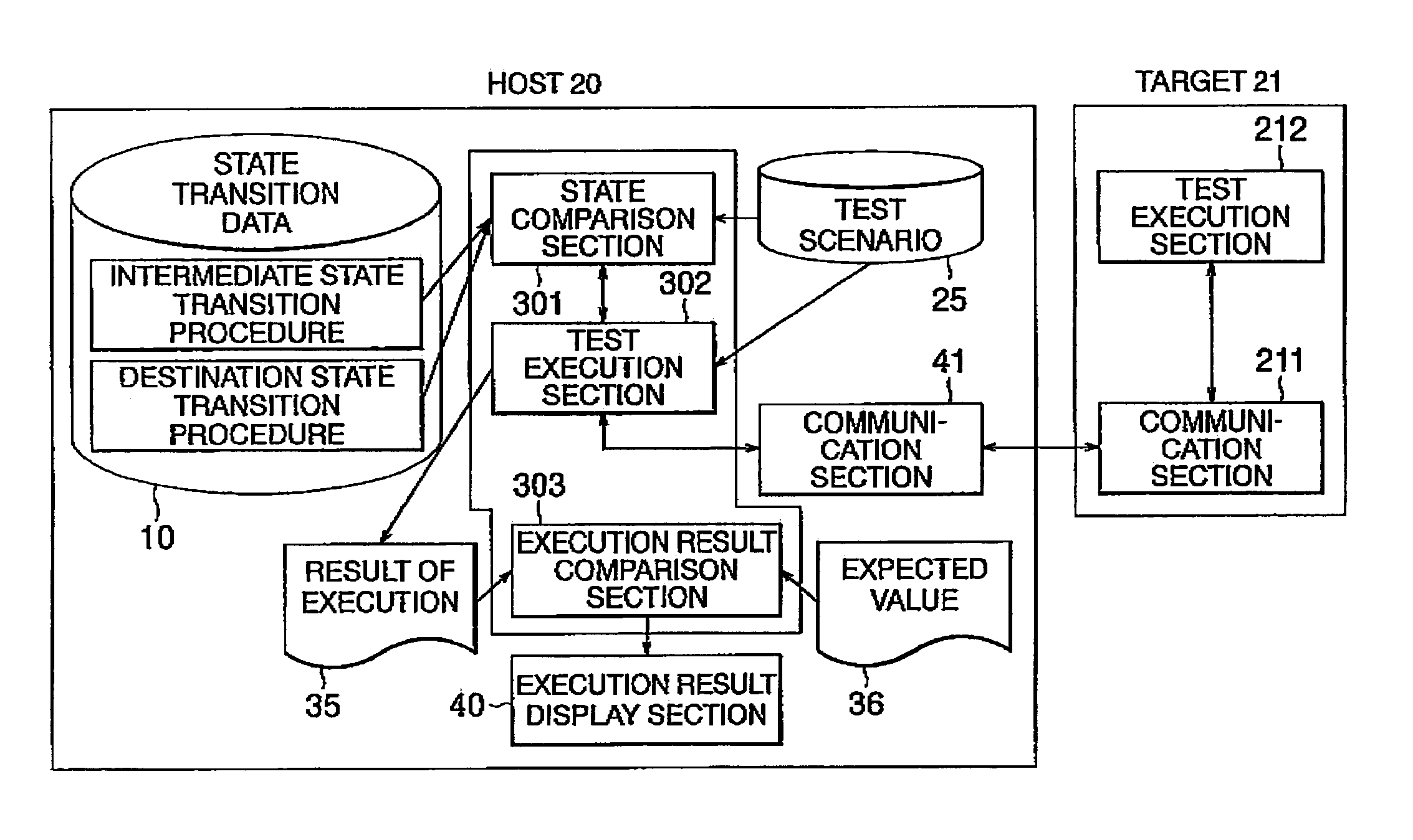
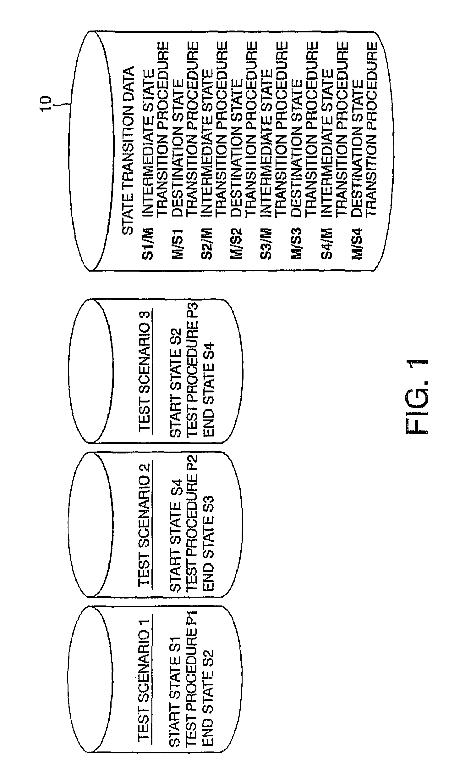
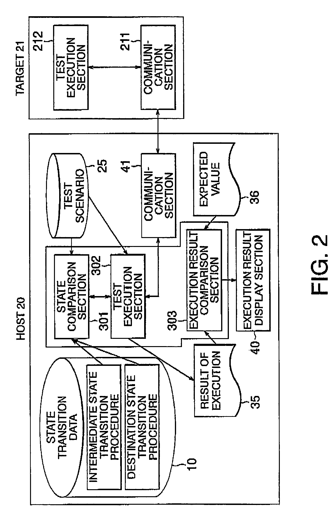
[0029]According to the present invention, for the transition from the state of the transition source to the state of the transition destination, the predetermined intermediate state is previously defined and the target causes a transition to occur from the state of the transition source to the intermediate state once and then it causes the transition to occur from the intermediate state to the state of the transition destination. In this manner, the state transition via the intermediate state reduces the number of definitions of the state transition procedures and enables an easy response to an increase or a decrease in the number of states or other changes. Therefore, the test system of the present invention is capable of easily testing an electronic device having a large number of states to be tested and whose functions may be frequently changed and can cope with a change in the order of executing the test scenarios.

Problems solved by technology

In any case, the practically used test method has a disadvantage that it cannot respond flexibly to an increase or a change in units included in a target to be tested.

Method used


Image

  • Test method, test system, and program therefor
  • Test method, test system, and program therefor
  • Test method, test system, and program therefor

Examples


first embodiment

[0050](First Embodiment)

[0051]The following describes the test system specifically according to an embodiment of the present invention by referring to FIG. 2 and FIG. 3 in addition to FIG. 1. Referring to FIG. 2, there is shown a test system according to the embodiment of the present invention. The test system comprises a host computer 20 performing an automatic verification and a target 21 to be verified. The target 21 has a plurality of units such as a tuner and a cassette, MD, CD, or DVD recorder like a car audio system. A user can select units and states thereof arbitrarily by manipulating buttons. As a result of the selection, the target causes a transition to occur from a state (previous state) before the selection to a state (next following state)after the selection. The shown test system is helpful to test and verify all states that the user may select by manipulations or operations. In this embodiment, It is assumed that a state corresponding to the state before the button ...


PUM


Abstract

In a test system, a test method, and a program for use in verifying states in a target, a predetermined state is previously defined as an intermediate state among states which can be taken by the target. On causing a transition to occur in the target from a previous state to a next following state, the transition is caused to occur in the target from a previous state to the intermediate state. Then, the target makes the transition from the intermediate state to the next following state. For this purpose, the test system stores intermediate state transition procedures from the previous state to the intermediate one and a self-state transition procedure from the intermediate state to the next following state.

Description

BACKGROUND OF THE INVENTION[0001]1. Field of the Invention[0002]The present invention relates to a test system for use in testing an electronic device, such as a car audio system.[0003]2. Related Background Art[0004]In general, this type of electronic device is equipped with various units such as CD, cassette tape, MD, and DVD recorders in addition to a tuner. When manufacturing an electronic device including a plurality of units as stated above, it is necessary to execute a test to investigate whether various operations are performed normally in the units before shipment of the electronic device. The electronic device to be tested is hereinafter referred to as a target or a target device.[0005]On testing the target including the plurality of units, it is necessary to test all operations that a user is likely to utilize. Therefore, with an increase of the number of units included in the target, required test items enormously increase. As a practical matter, there is even a case that...

Claims


Application Information

Patent Timeline
Patent Type & Authority Patents(United States)
IPC IPC(8): G06F19/00G06F11/22G01D3/00G05B23/02G06F11/00
CPCG05B23/0256
Inventor MARUNO, KOJI
Owner NEC ELECTRONICS CORP
Learn More