Gear device

Inactive Publication Date: 2011-01-20
NABLESCO CORP
View PDF5 Cites 4 Cited by
  • Summary
  • Abstract
  • Description
  • Claims
  • Application Information

AI Technical Summary

Benefits of technology

[0010]It is an object of the present invention to suppress the occurrence of radial vibration in an end portion of the cylindrical body extending

Problems solved by technology

Therefore, most of the cylindrical body 118 has to be subjected to cutting in a length direction the

Method used


Image

  • Gear device
  • Gear device
  • Gear device

Examples


Example

First Embodiment

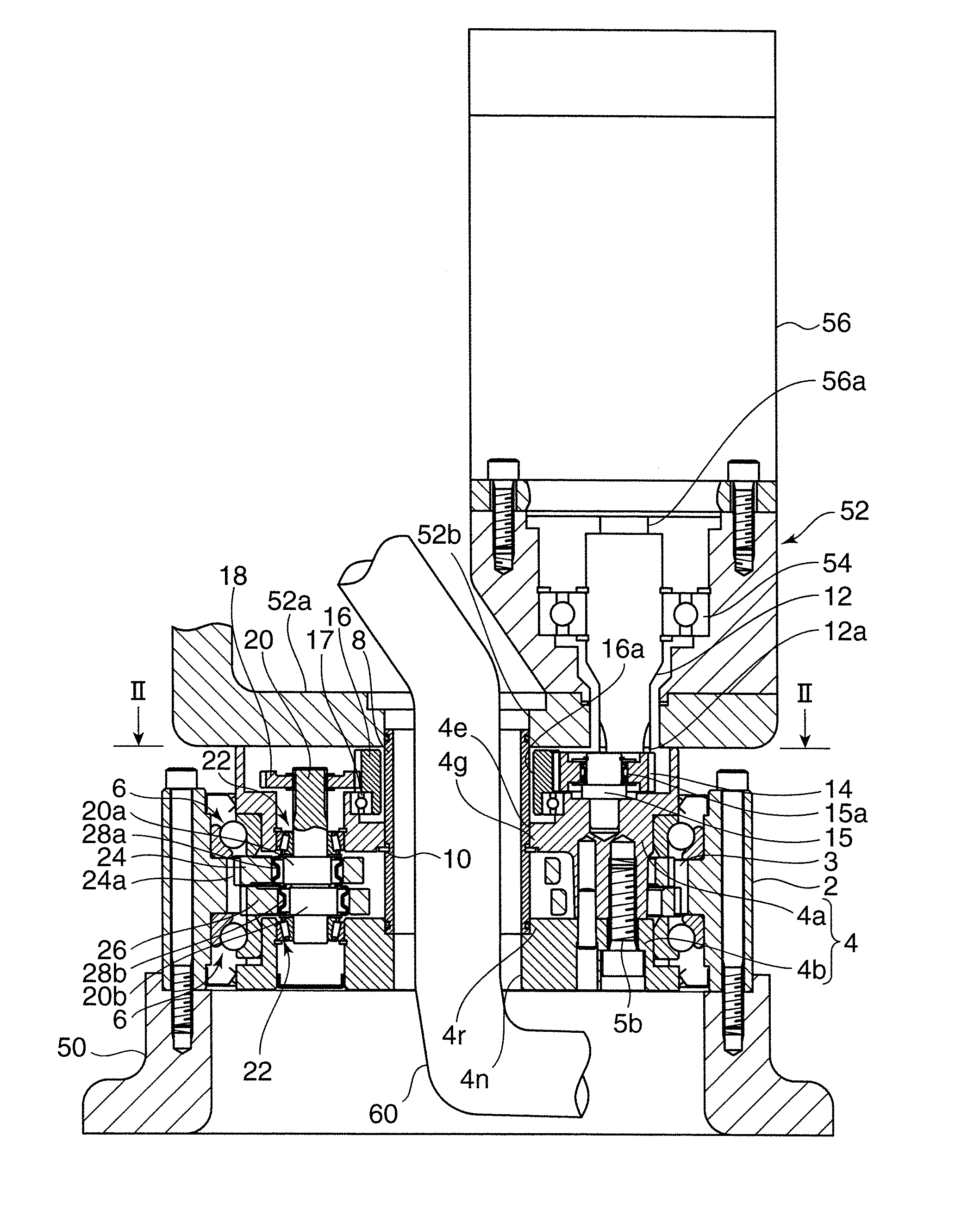
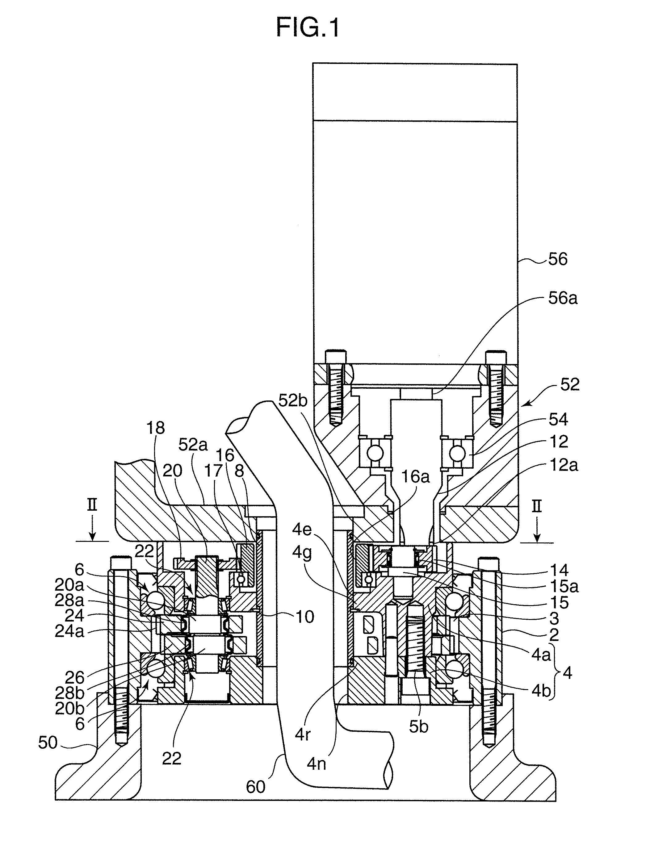
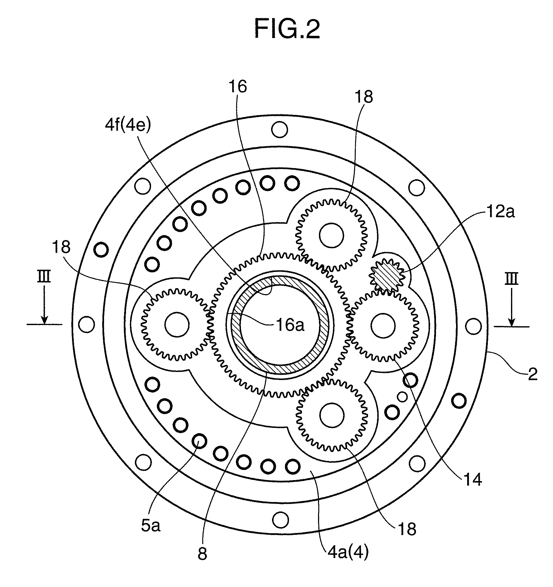
[0018]Firstly, with reference to FIGS. 1 to 3, a structure of a gear device according to a first embodiment of the present invention will be described.

[0019]The gear device according to the first embodiment is used, for example, as a speed reducer in turning sections such as a turning body and an arm joint of a robot, or turning sections of various machine tools. The following description of the first embodiment will be made about one example where the gear device is used in a turning body of a robot.

[0020]As shown in FIG. 1, the gear device according to the first embodiment is adapted to be capable of transmitting rotational force between a base 50 and a turning body 52 at a predetermined speed reduction ratio. The base 50 is encompassed in a concept of one of a pair of mating members in the appended claims, and the turning body 52 is encompassed in a concept of the other mating member in the appended claims. The gear device according to the first embodiment compris...

Example

Second Embodiment

[0061]With reference to FIG. 4, a structure of a gear device according to a second embodiment of the present invention will be described below.

[0062]The gear device according to the second embodiment is different from the gear device according to the first embodiment in the following points. A cylindrical body 8 is fixed to a carrier 4 in such a manner that it is kept from being moved in a rotation direction and an axial direction thereof by a sealing ring 9a installed in a lower end portion of the cylindrical body 8 to which a first portion 4r of the carrier 4 is externally fitted, and a sealing ring 9d installed in an axially intermediate portion of the cylindrical body 8 to which a second portion 4g of the carrier 4 is externally fitted.

[0063]Specifically, in the second embodiment, a basal segment 4a and an end plate segment 4b of the carrier 4 are disposed upside down as compared with the first embodiment. Further, a basal plate portion 4c of the basal segment 4...


PUM


Abstract

A gear device has an outer cylinder fixed to a first mating member and a crankshaft inside the outer cylinder. An external gear is mounted to an eccentric portion of the crankshaft and meshes with internal teeth of the outer cylinder. A carrier is fixed to a second mating member. Rocking rotation of the external gear rotates the carrier coaxially to the outer cylinder. A cylindrical body is inserted in an axial through-hole of the carrier. The carrier has a first portion on one end of the cylindrical body and a second portion on an axially intermediate portion of the cylindrical body. The other end of the cylindrical body extends toward a corresponding mating member while protruding axially beyond the second portion. An outer diameter of remaining portions of the cylindrical body do not exceed an outermost diameter of the portion on which the first and second portions are fit.

Description

BACKGROUND OF THE INVENTION[0001]1. Field of the Invention[0002]The present invention relates to a gear device.[0003]2. Description of the Related Art[0004]Heretofore, there has been known a gear device designed to obtain an output rotation at a speed reduced from an input rotation by allowing an external gear to be rockingly rotated while being meshed with internal teeth of an outer cylinder, according to an eccentric portion of a crankshaft. One example of this type of gear device is disclosed in the JP 2002-106650.[0005]FIG. 5 is a vertical sectional view of a gear device disclosed in the JP 2002-106650. In this gear device, a crankshaft 104 having two eccentric portions 104a, 104b arranged in side-by-side relation in an axial direction thereof is provided inside an outer cylinder 102 in a rotatable manner about an axis thereof. Although not illustrated in FIG. 5, a similar crankshaft other than the crankshaft 104 is also provided inside the outer cylinder 102, and these cranksha...

Claims


Application Information

Patent Timeline
IPC IPC(8): F16H1/32
CPCF16H2001/323F16H1/32
Inventor NAKAMURA, KOJIIMAI, MASASHIFUJIMOTO, KENICHI
Owner NABLESCO CORP
Why Eureka
Try Eureka