
Analog to digital converter

a converter and analog technology, applied in the direction of digital-analog converters, physical parameters compensation/prevention, power saving provisions, etc., can solve the problems of rapid increase in delay time and power consumption required for driving the ad converter, and the size of the device and its simplification is limited, so as to prevent the increase in delay time and power consumption

Inactive Publication Date: 2018-11-06
LSIS CO LTD
View PDF26 Cites 3 Cited by
  • Summary
  • Abstract
  • Description
  • Claims
  • Application Information

AI Technical Summary

Benefits of technology

[0014]It is an aspect of the present disclosure to provide an AD converter capable of preventing the increase in delay time and power consumption, while coping with a plurality of resolutions.
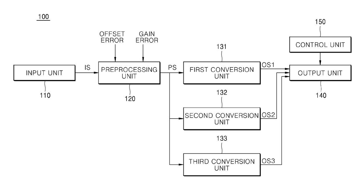
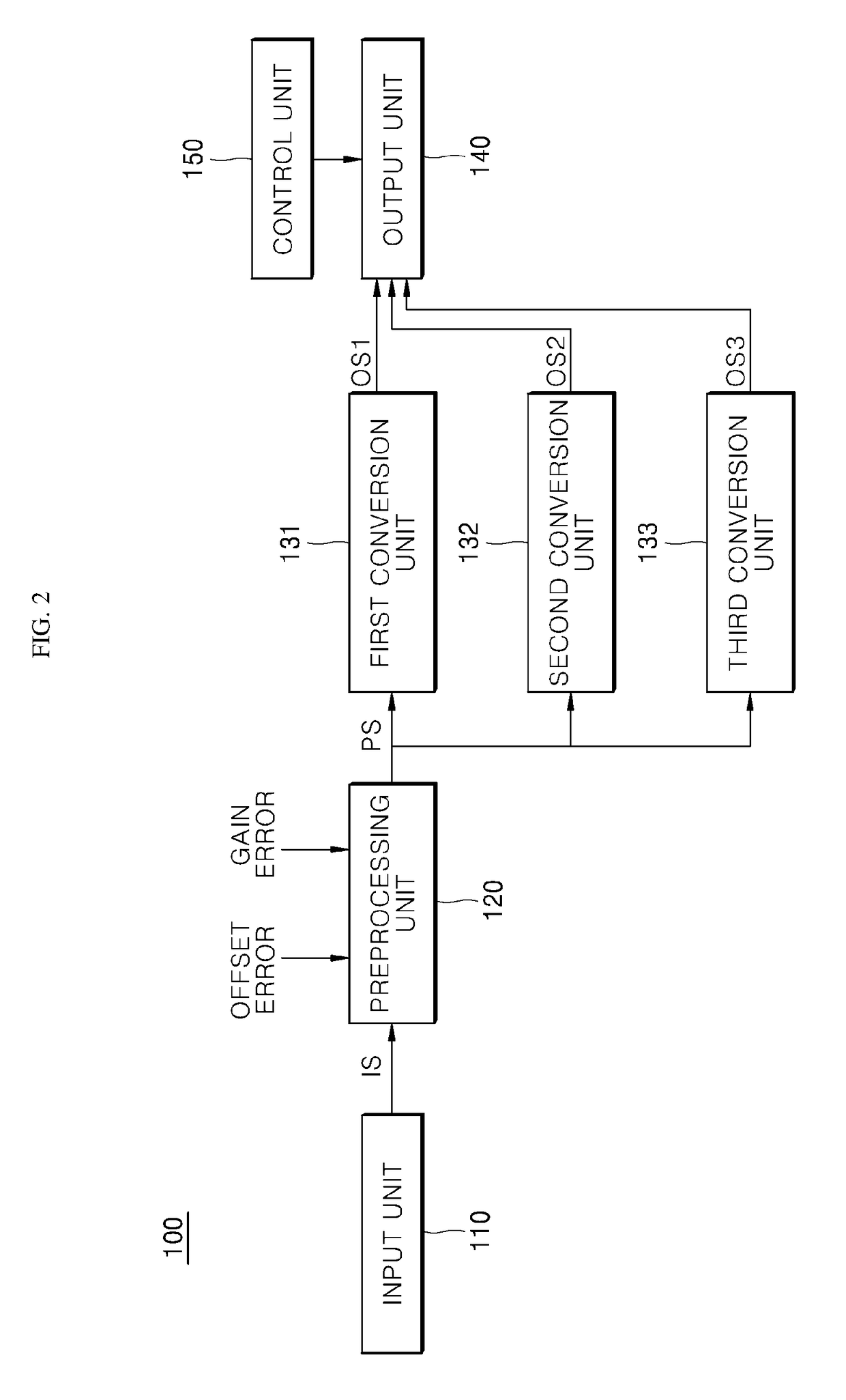
[0019]According to the present disclosure, the AD converter converts the input signal into the preprocessing signal having the first bit number and then converts the preprocessing signal into the first output signal having the second bit number smaller than the first bit number or into the second output signal having the third bit number smaller than the first bit number. That is, the AD converter does not convert the input signal into the first output signal having the second bit number or the second output signal having the third bit number. Instead, the AD converter converts the preprocessing signal having the first bit number into the first output signal or the second output signal through an operation of reducing the number of bits. Here, the operation of reducing the number of bits can be performed relatively simply through a bit shift operation.
[0020]Accordingly, each conversion unit for converting the preprocessing signal into the first or second output signal can be implemented with a relatively simple circuit, which is advantageous for device miniaturization and simplification.
[0021]In addition, since the conversion operation from the preprocessing signal into the first or second output signal is relatively simple, it is possible to prevent a rapid increase in delay time and power consumption required for the conversion operation even when the number of output signals having different resolutions increases.

Problems solved by technology

However, when the conventional AD converter provides various resolutions for improving efficiency and compatibility, there is a problem that the device size and simplification are limited due to the inclusion of a conversion unit for each resolution.
Therefore, as the resolution of the AD converter increases, there is a problem that the delay time and power consumption required for driving the AD converter may rapidly increase.

Method used


Image

  • Analog to digital converter
  • Analog to digital converter
  • Analog to digital converter

Examples


Embodiment Construction

[0025]The above objects, features and advantages will become more clearly apparent from the following detailed description in conjunction with the accompanying drawings. Therefore, the technical ideas of the present disclosure can be easily understood and practiced by those skilled in the art. In the following detailed description of the present disclosure, concrete description on related functions or constructions will be omitted if it is deemed that the functions and / or constructions may unnecessarily obscure the gist of the present disclosure. Hereinafter, preferred embodiments of the present disclosure will be described in detail with reference to the accompanying drawings. Throughout the drawings, the same or similar elements are denoted by the same reference numerals.

[0026]Hereinafter, an AD converter according to an embodiment of the present disclosure will be described in detail with reference to the accompanying drawings.

[0027]First, an analog input module including an AD c...


PUM


Abstract

An A / D converter includes: an input unit configured to receive an analog input signal, a preprocessing unit configured to convert the input signal into a digital preprocessing signal based on a dynamic range of the input signal and a first resolution corresponding to a predetermined first bit number, a first conversion unit configured to convert the preprocessing signal into a first output signal based on a second resolution corresponding to a second bit number smaller than the first bit number, and a second conversion unit configured to convert the preprocessing signal into a second output signal based on a third resolution corresponding to a third bit number which is smaller than the first bit number and is different from the second bit number.

Description

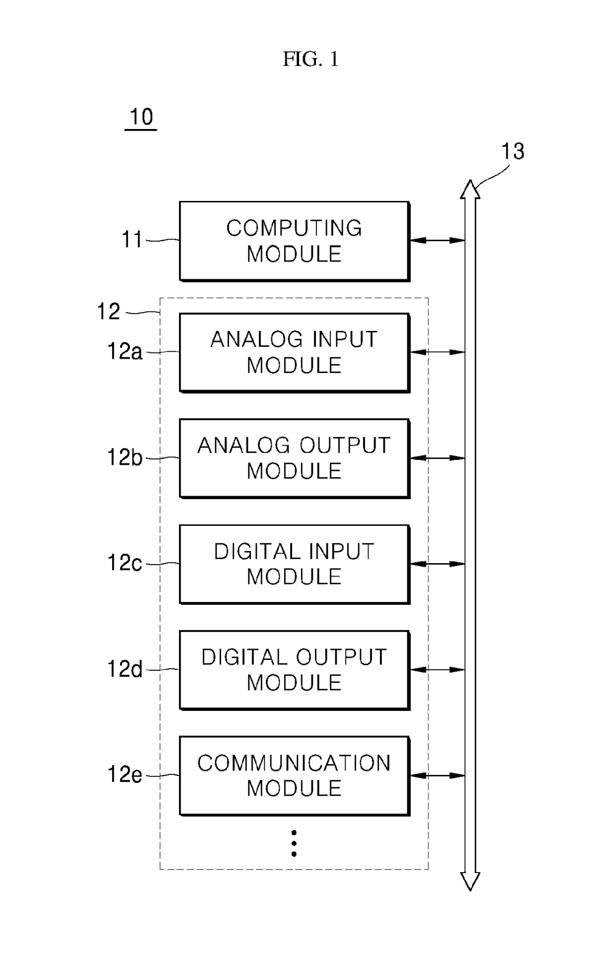
CROSS-REFERENCE TO RELATED APPLICATIONS[0001]Pursuant to 35 U.S.C. § 119(a), this application claims the benefit of earlier filing date and right of priority to Korean Patent Application No. 10-2017-0043269 filed on Apr. 3, 2017, in the Korean Intellectual Property Office, the disclosure of which is hereby incorporated by reference in its entirety.BACKGROUND1. Technical Field[0002]The present disclosure relates to an analog to digital (AD) converter for converting an analog signal into a digital signal, and more particularly to an AD converter that may be included in an analog input module of a programmable logic controller (PLC).2. Description of the Related Art[0003]Recently, in realizing the automation equipment, relays for sequentially connecting control target devices performing their respective processes according to the order of processes have been replaced by PLCs (Programmable Logic Controllers).[0004]A PLC system is a system for driving and controlling the control target d...

Claims


Application Information

Patent Timeline
Patent Type & Authority Patents(United States)
IPC IPC(8): H03M1/66H03M1/06H03M1/18
CPCH03M1/066H03M1/18H03M1/0604H03M1/002H03M1/005H03M1/1205H03M1/0609H03M1/186H03M1/188H03M1/34
Inventor KIM, JUNG-WOOK
Owner LSIS CO LTD
Learn More