Drive control device for a display apparatus, video image display apparatus and method of controlling the driving of the video image display apparatus
a technology of video image display and control device, which is applied in the direction of television system, selective content distribution, instruments, etc., can solve the problems of user's visual annoyance from a change in the brightness of the overall screen, user's strangeness, control value continues to change, etc., to prevent the increase in power consumption and heating of the display surface, and not cause visual annoyance.
- Summary
- Abstract
- Description
- Claims
- Application Information
AI Technical Summary
Benefits of technology
Problems solved by technology
Method used
Image
Examples
first embodiment
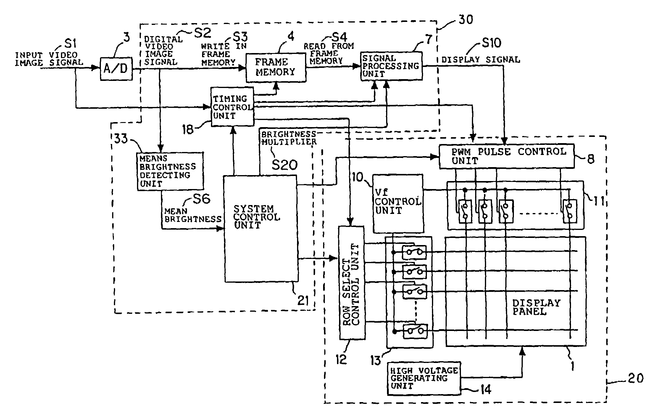
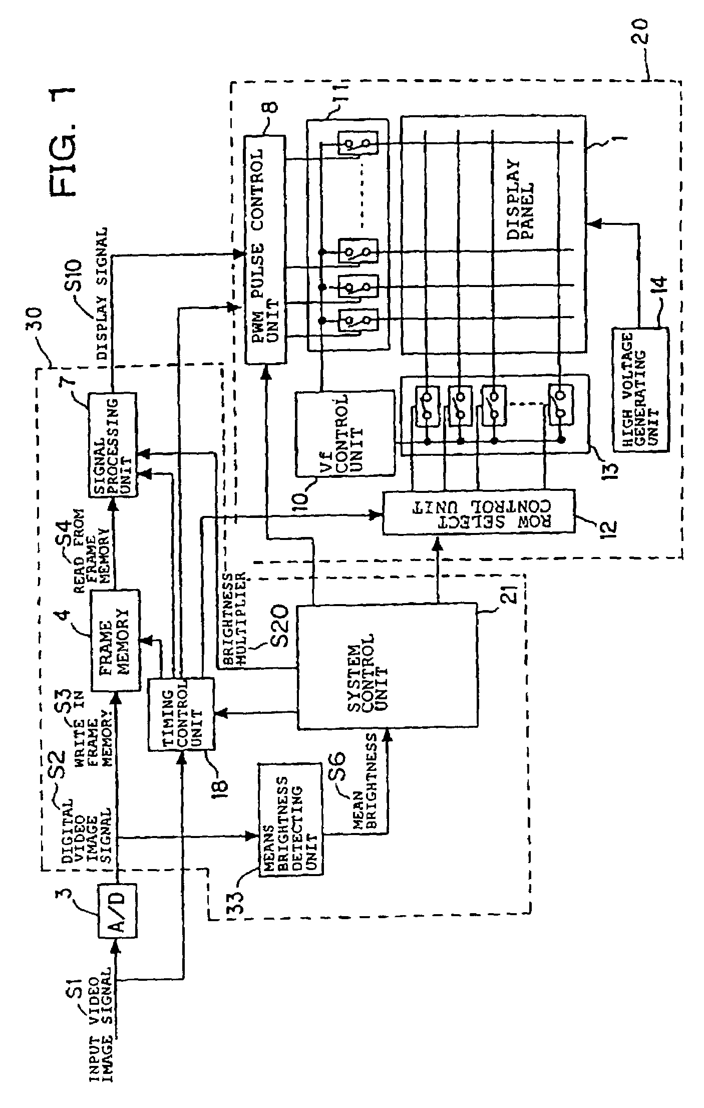
[0031]FIG. 1 shows the structure of a video image display apparatus in accordance with a first embodiment.
[0032]Referring to FIG. 1, reference numeral 1 denotes a display panel, and in this embodiment, there is employed a display panel including a large number of electron sources on a substrate, for example, multiple electron sources having surface conduction type cold cathode elements arranged therein and an image forming member that forms an image by irradiating electrons, which are opposed to each other.
[0033]Surface conduction type electron emitting elements are wired in a simple matrix by row-directional wiring electrodes and column-directional wiring electrodes, and electrons emitted from an electron emitting element selected by a column / row electrode bias are accelerated by a high voltage so as to be made to collide with phosphors, to thereby emit a light.
[0034]The structure of the display panel and a display panel manufacturing method are disclosed in detail in JP 2000-25046...
second embodiment
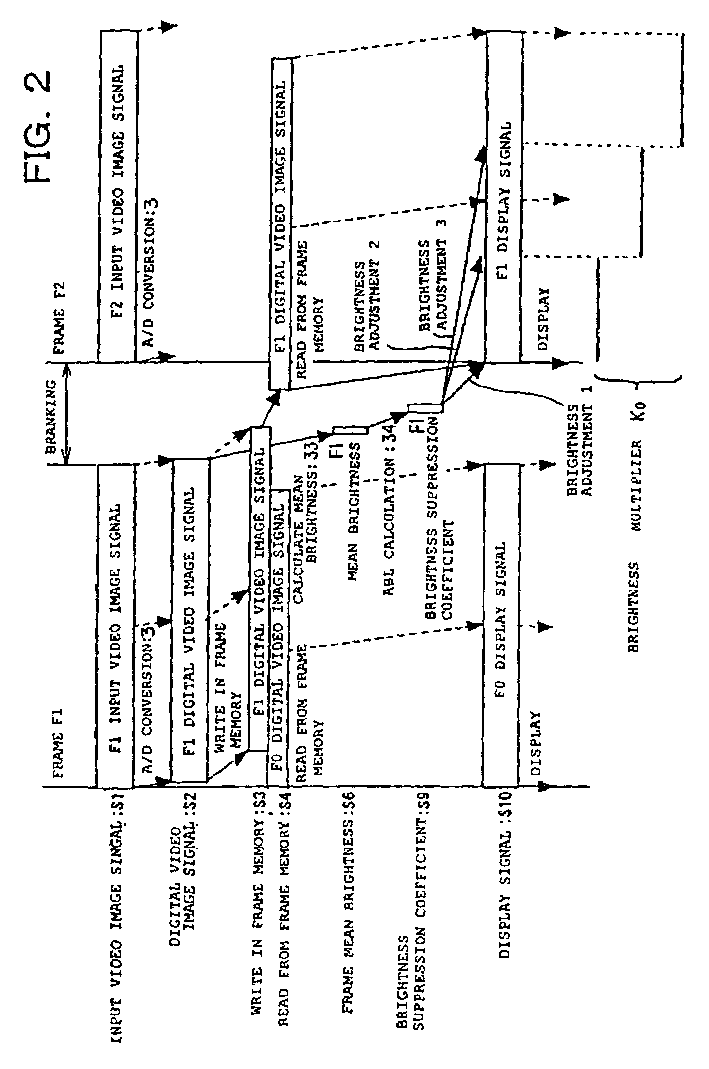
[0077]In the first embodiment, the output interval of the brightness multiplier is calculated on the basis of the expression 3 from the inter-frame difference of the brightness suppression coefficient, however, in this embodiment, the output interval C of the brightness multiplier is set to a predetermined constant value.
[0078]A thin line in FIG. 4C is a graph showing a change in the brightness multiplier Ko in the case where the output interval C of the brightness multiplier is Yn / 16 in correspondence with FIG. 4A. In this embodiment, since a timing at which the brightness multiplier changes is concentrated in the front half of the one-frame scanning period, the arrival at the brightness multiplier which is desired, that is, the desired brightness multiplier value K′ (t) becomes quick.
[0079]Other matters are identical with those in the first embodiment, and the flowchart of FIG. 3 is identical with that of the first embodiment except that the brightness multiplier output interval c...
third embodiment
[0083]In this embodiment, in the case where the mean brightness of the display screen is high, the power consumption becomes large so as to apply a load onto the high-voltage generating unit 14, and therefore a response speed of the ABL is going to be made high, depending on the characteristics of the video image display apparatus. However, in the case where the brightness is low, in particular, when it is unnecessary that the response speed of the ABL is high, this embodiment is preferred. In this case, a time constant is set to different values between a time when the brightness suppression coefficient is increased and a time when the coefficient is decreased, to thereby control a period of time where the brightness multiplier value reaches the desired brightness multiplier value K′ (t).
[0084]In this case, a time constant is set to different values between a time when the brightness suppression coefficient is increased and a time when the coefficient is decreased, to thereby contr...
PUM
 Abstract
Description
Claims
Application Information
 - R&D
- Intellectual Property
- Life Sciences
- Materials
- Tech Scout
- Unparalleled Data Quality
- Higher Quality Content
- 60% Fewer Hallucinations
Browse by: Latest US Patents, China's latest patents, Technical Efficacy Thesaurus, Application Domain, Technology Topic, Popular Technical Reports.
© 2025 PatSnap. All rights reserved.Legal|Privacy policy|Modern Slavery Act Transparency Statement|Sitemap|About US| Contact US: help@patsnap.com


