Control device for switching power source

a technology of control device and power source, which is applied in the direction of power conversion system, dc-dc conversion, instruments, etc., can solve problems such as power consumption increas

Active Publication Date: 2015-07-30
FUJI ELECTRIC CO LTD
View PDF7 Cites 6 Cited by
  • Summary
  • Abstract
  • Description
  • Claims
  • Application Information

AI Technical Summary

Benefits of technology

[0019]However, in a configuration in which a shunt regulator and digital control unit are combined as shown in FIG. 8, the output voltage oscillates as described previously, and even in a normal state, the A/D conversion output (DPWM input) does not remain constant. In other words, the input during the period during which the dither sum is determined does not necessarily remain constant, and therefore, variation

Problems solved by technology

However, if the number of bits of data used in a digital counter type DPWM circuit is increased by Npwm, t

Method used


Image

  • Control device for switching power source
  • Control device for switching power source
  • Control device for switching power source

Examples


Embodiment Construction

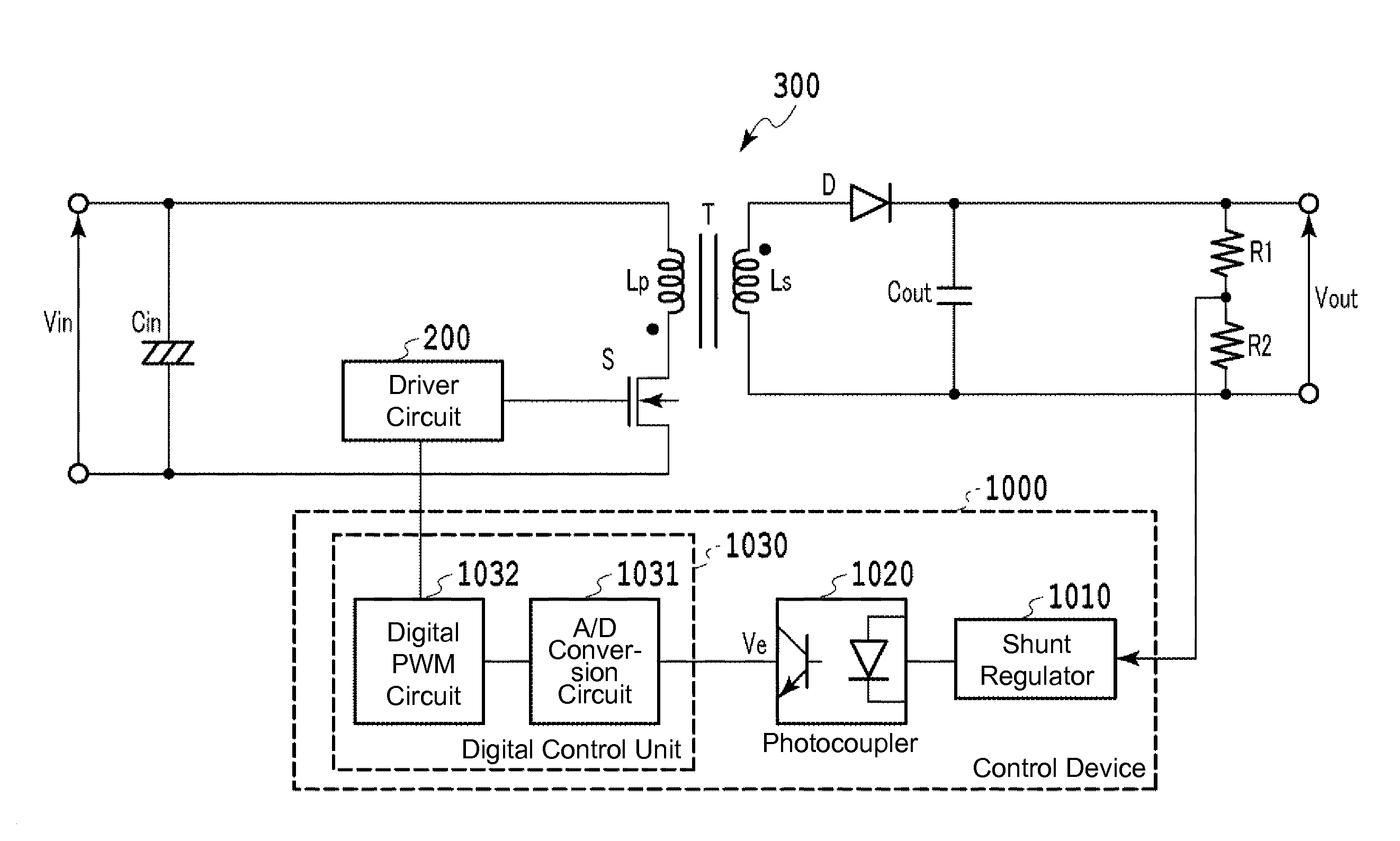
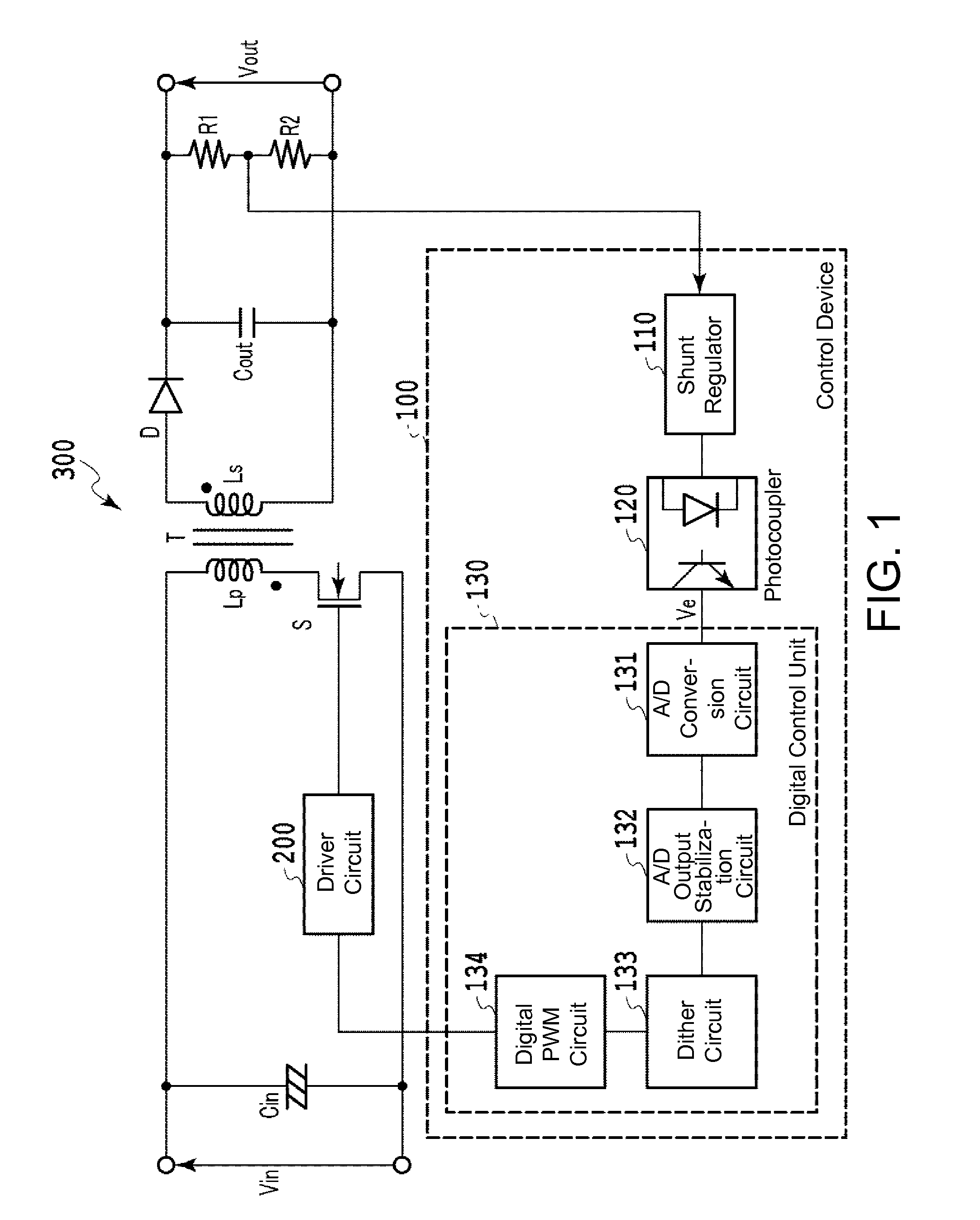
[0040]FIG. 1 shows an insulation type DC / DC converter and a control device thereof according to one embodiment of the present invention. A control device 100 of an insulation type DC / DC converter 300 includes a shunt regulator 110 that detects an error in output voltage at the secondary side of a transformer, a photocoupler 120 that transmits the detected error voltage to the primary side of the transformer, and a DPWM control unit 130 on the primary side that generates a control pulse signal having a pulse width at a duty ratio based on the error voltage.

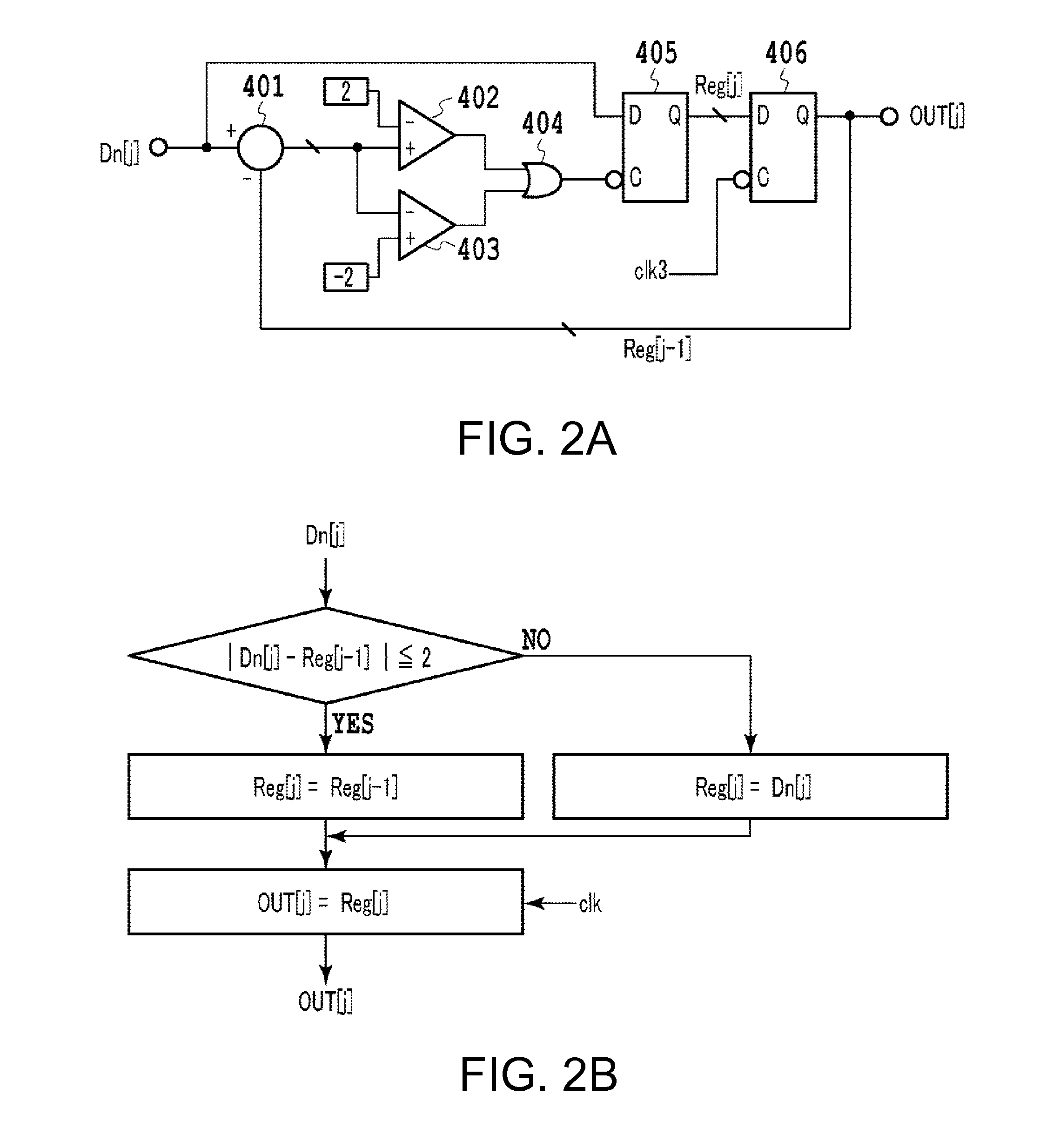
[0041]The DPWM control unit 130 includes an A / D conversion circuit 131, an A / D output stabilization circuit 132, a dither circuit 133, and a DPWM circuit 134. The A / D output stabilization circuit 132 is provided after the A / D conversion circuit 131, and the output end of the A / D output stabilization circuit 132 is connected to the input end of the dither circuit 133.

[0042]In an embodiment of the present invention also, the dither c...


PUM


Abstract

A control device of an insulation type DC/DC converter includes a shunt regulator that detects an error in output voltage at the secondary side of a transformer, a photocoupler that transmits the detected error voltage to the primary side of the transformer, and a DPWM control unit on the primary side that generates a control pulse signal having a pulse width at a duty ratio based on the error voltage. The DPWM control unit includes an A/D conversion circuit, an A/D output stabilization circuit, a dither circuit, and a DPWM circuit. The A/D output stabilization circuit is provided after the A/D conversion circuit, and the output end of the A/D output stabilization circuit is connected to the input end of the dither circuit.

Description

BACKGROUND OF THE INVENTION[0001]1. Technical Field[0002]The present invention relates to a control device for mitigating output voltage oscillation in a switching power source that performs digital control.[0003]2. Background Art[0004]As shown in FIG. 6, conventional insulation type DC / DC converters include, in the secondary side of a transformer that outputs a prescribed voltage, a shunt regulator 710, an error amplifier, or the like that outputs an error voltage in which a difference between the output voltage and a target voltage is amplified, and additionally include an insulating element such as a photocoupler 720 or the like for sending the detected error voltage to the primary side of the transformer.[0005]The primary side of the transformer includes a pulse width modulation (PWM) circuit 730, which generates a control pulse signal having a pulse width at a duty ratio based on the error voltage, and a desired output voltage is attained by controlling a switching element by t...

Claims


Application Information

Patent Timeline
IPC IPC(8): H02M3/335
CPCH02M3/33507H02M3/33523H02M1/0012
Inventor KAWASHIMA, TETSUYA
Owner FUJI ELECTRIC CO LTD
Why Eureka
Try Eureka