Power transmission apparatus

a technology of power transmission and transmission shaft, which is applied in the direction of gearing, transportation and packaging, tractors, etc., can solve the problems of degrading the power transmission efficiency to the drive wheel side, degrading the fuel consumption rate, etc., and reducing the efficiency of the power transmission

Active Publication Date: 2018-02-01
SUBARU CORP
View PDF0 Cites 6 Cited by
  • Summary
  • Abstract
  • Description
  • Claims
  • Application Information

AI Technical Summary

Benefits of technology

[0017]The control unit may be configured to increase an electric power generation amount by the first motor generator, eliminate the engine power that is transmitted through coupling by an origin...

Problems solved by technology

However, in a vehicle for which the winding CVT is adopted, relatively high hydraulic pressure is required for actuation control of a torque converter and hydraulic control to drive the pulleys, which leads to a degraded fuel consumption rate (hereinafter “fuel consumption”) of the engine as a drive source for an oil pump and to degraded power transmission efficiency to the drive wheel side.
Because the clutch is a mechanism, friction of which is assumed, the clutch is relatively and severely deteriorated by age.
In addition, because the clutch generates a relatively large amount of heat at the start,...

Method used


Image

  • Power transmission apparatus
  • Power transmission apparatus
  • Power transmission apparatus

Examples


Embodiment Construction

[0025]

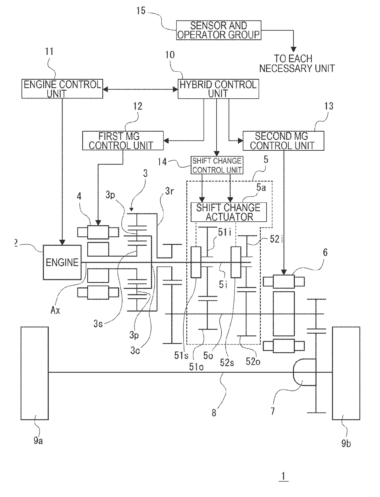
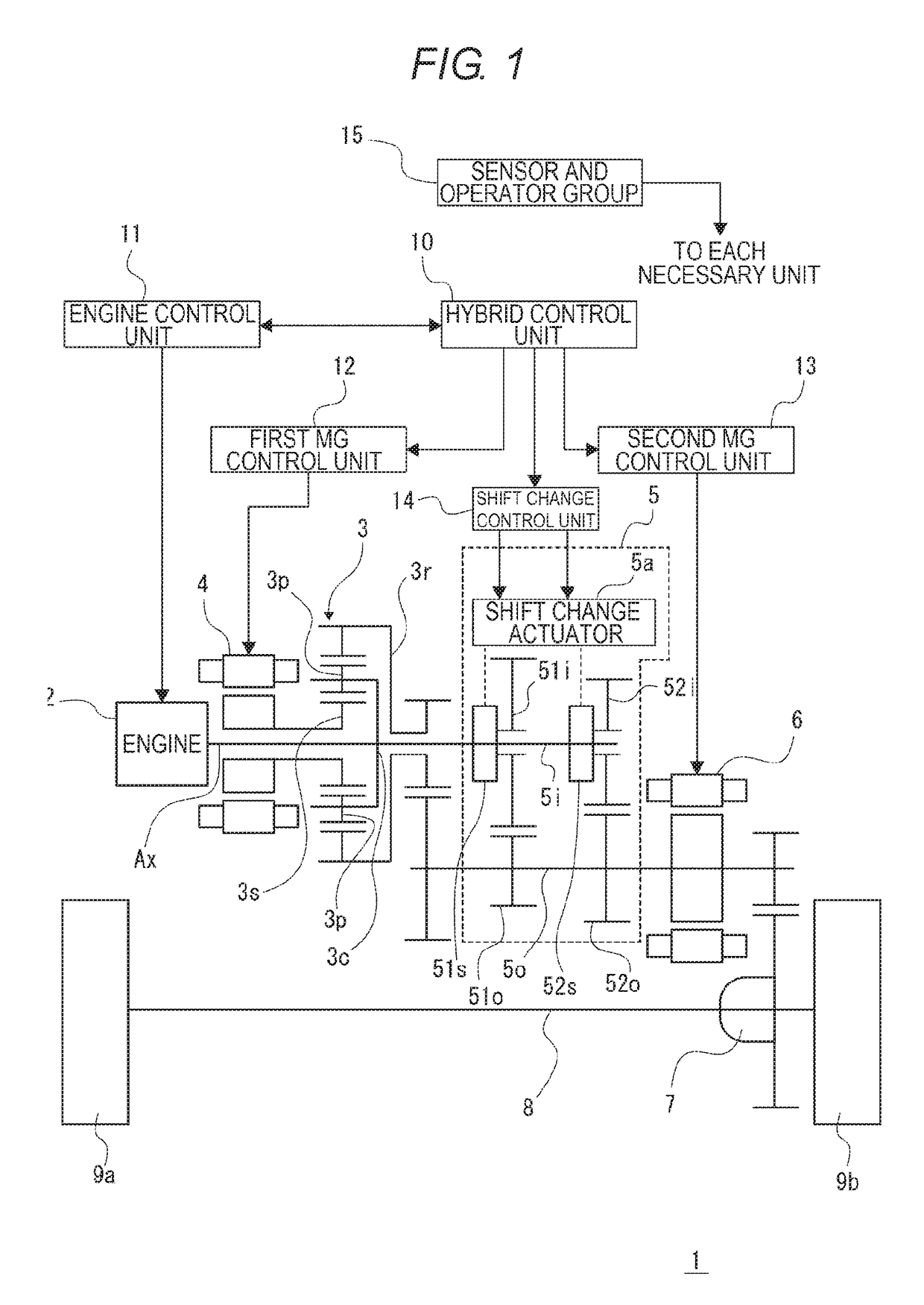
[0026]FIG. 1 is a view that schematically illustrates a configuration of a vehicle 1 including a power transmission apparatus as an example according to the present invention. Note that, of the configuration of the vehicle 1, only configurations of main components related to the present invention are mainly extracted and illustrated in FIG. 1.

[0027]In FIG. 1, the vehicle 1 includes: an engine 2; a power input shaft Ax that is coupled to a crankshaft (not illustrated) as a power output shaft of the engine 2 and receives power from the engine 2; a planetary gear mechanism 3 that can receive the power of the engine 2 via the power input shaft Ax; a first motor generator 4; a stepped automatic transmission 5 with parallel gears; a second motor generator 6; a differential gear 7; a drive shaft 8; a drive wheel 9a; and a drive wheel 9b.

[0028]Note that the “motor generator” will hereinafter be abbreviated as an “MG”.

[0029]The planetary gear mechanism 3 includes: a sun gear 3s as an ...


PUM


Abstract

A power transmission apparatus that is mountable on a vehicle includes a planetary gear mechanism, a first motor generator, a second motor generator, and a stepped automatic transmission with parallel gears. The first motor generator and an output side shaft of the stepped automatic transmission are configured to be coupled to a power input shaft from an engine provided in the vehicle via the planetary gear mechanism. An input side shaft of the stepped automatic transmission is configured to be coupled to the power input shaft. The second motor generator is coupled to the output side shaft of the stepped automatic transmission.

Description

CROSS-REFERENCE TO RELATED APPLICATIONS[0001]The present application claims priority from Japanese Patent Application No. 2016-146580 filed on Jul. 26, 2016, the entire contents of which are hereby incorporated by reference.BACKGROUND1. Technical Field[0002]The present invention relates to a technical field of a power transmission apparatus that includes a stepped automatic transmission with parallel gears.2. Related Art[0003]As a power transmission apparatus that transmits power from an engine to a drive wheel side in a vehicle, a power transmission apparatus that includes an automatic transmission has been known. In recent years, a winding continuously variable transmission (CVT) in which a winding member, such as a metal belt or chain, is wound around opposing pulleys has widely been spread as the automatic transmission, for instance. The automatic transmission of this kind can seamlessly adjust a transmission gear ratio and thus has such an advantage that it can efficiently use ...

Claims


Application Information

Patent Timeline
IPC IPC(8): B60W10/115B60W20/20F16H59/68B60K28/16B60L50/16
CPCB60W10/115B60K28/165B60W20/20F16H59/68B60K28/10B60W10/06F16H2059/6892B60K6/547B60W20/30B60W20/19B60W10/10F16H61/456B60W20/15B60K6/365B60K6/40B60W10/08B60W2510/06B60W2510/0638B60W2540/10B60W2510/104B60W2520/10B60W2520/105B60W2710/1005B60W2710/08B60W2710/06F16H61/0403B60Y2200/92F16H2061/0422F16H2061/0433B60K6/445B60W10/105B60W10/11B60W30/1843B60W2510/087B60K6/36B60K6/387F16H2200/0034F16H3/089Y02T10/62F16H61/36
Inventor ISHIKAWA, MASATOSHI
Owner SUBARU CORP
Why Eureka
Try Eureka